This is my build log of Siegfried Linkwitz’s latest and best open baffle dipole loudspeaker design – the LX521.4.
My relationship with SL’s designs goes back a fair way… my good friend Pete Johnson at medical school drew my attention to Siegfried’s Wireless World active crossover system some 30 years or more ago – we both decided to build one. Pete was a whizz at electronics, whereas I was more comfortable working with wood (thanks, Dad!). Last year for some reason I found myself wondering whether Siegfried was still alive and active in the audio field and searched out his website . It did not take me long to decide to build the LX521s – my old WW system had fallen into disrepair and had been consigned to the garage years earlier (I have renovated it since – separate page to follow).
I hope the log will both inspire and help others to build their own LX521s. I’ve not even heard them yet! – but everything I have read suggests I won’t be disappointed when they are finally up and running.
The woofer boxes are made from 18mm BB grade birch ply – I sourced these from Woodcraft in St Neots as they offered an accurate cut-to-size service, with a tolerance of around 0.5mm. I had redrawn the woofer plans converting measurements to metric (details not given here as copyright to SL).
The planed mitres
When I picked up the order (plus offcuts – needed for the upper baffle mount) I was pleased to find no planing was required at all, and all panels were nice and square. Good decision. I had already marked and jig-sawed out the woofer holes and drilled their mounting holes before I got to grips with Wordpress; bar the dowels the only other preparation was to plane the45deg mitres on the lower V-frames and the top filler pieces.
SCREWS OR DOWELS?
I decided on dowels partly because of the considerably increased strength these impart, and partly to keep the external surfaces as pristine as possible for the sake of a good finish. I am aware that some building the LX521s have opted for screw and glue; in the end perhaps it is a trade off between spending your time marking and drilling dowel holes or filling endless countersunk screw holes.
DOWEL JIG OR MARK OUT?
Dowel jig
My next decision was whether to mark and drill them all individually, or whether to fabricate a jig to speed the process. Some experimentation followed; this is the Mark 2 jig made from some spare hardwood which I used to drill the first box. Modified rapture – despite carefully screwing the jig to each joint line I experienced some unpredictable drill wander. Some joints came out perfectly whereas others were distinctly off, requiring tedious adjustment of dowel holes to bring things back into line.
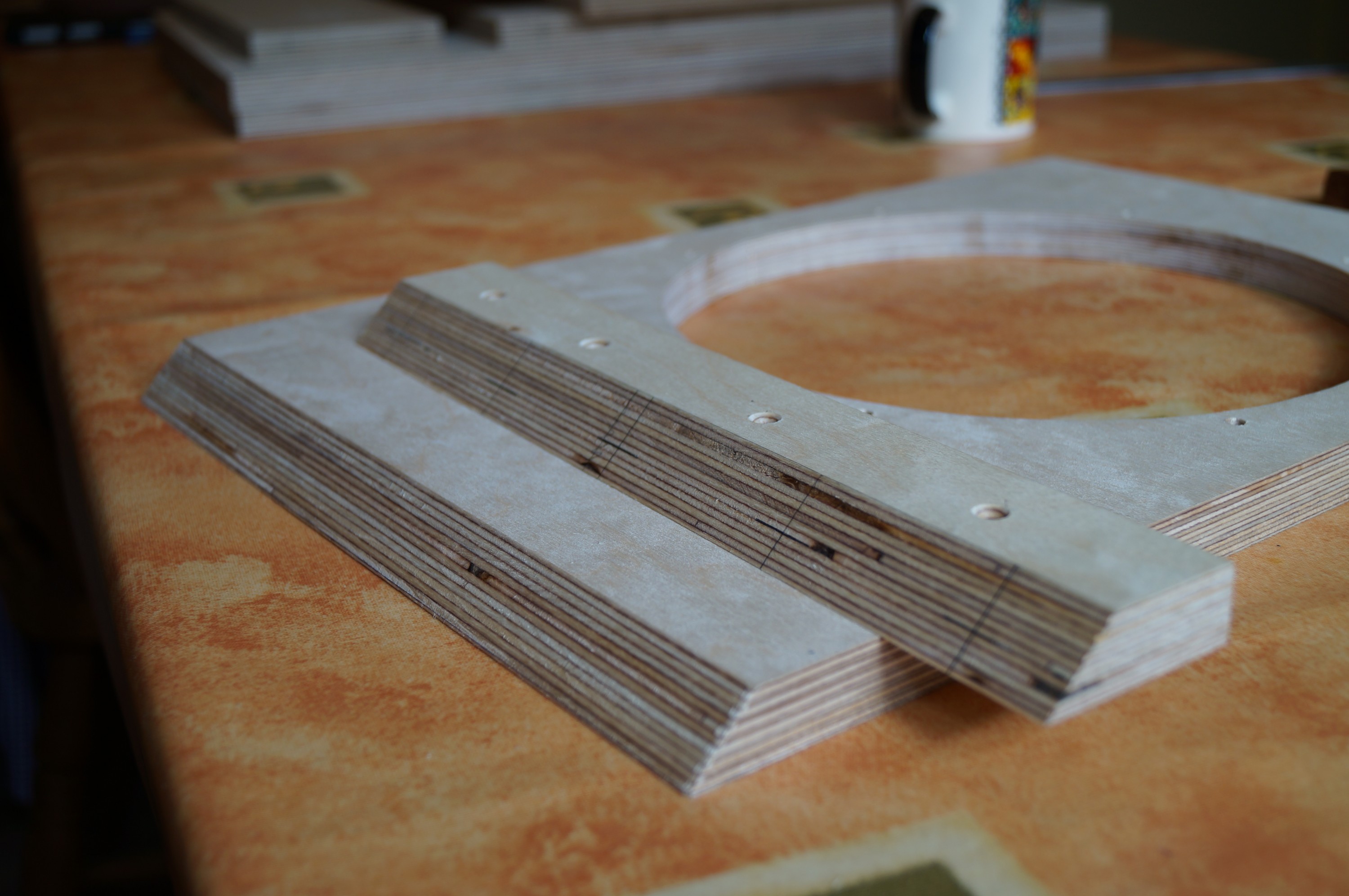
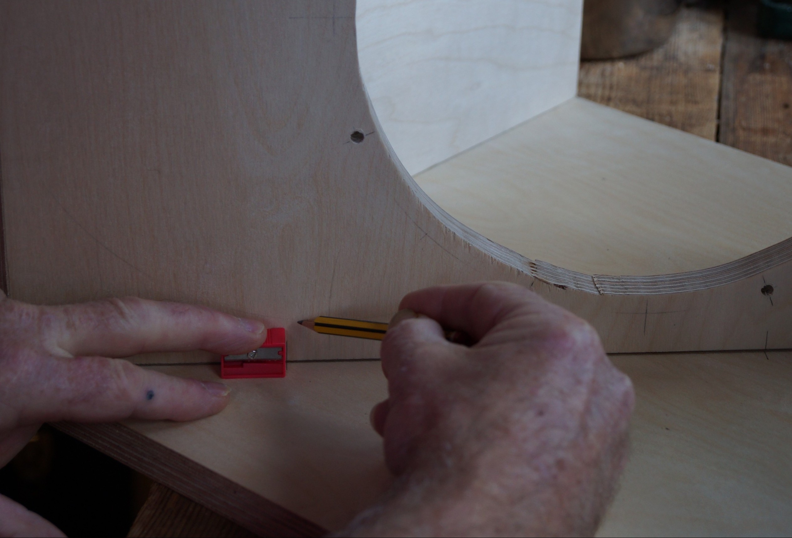
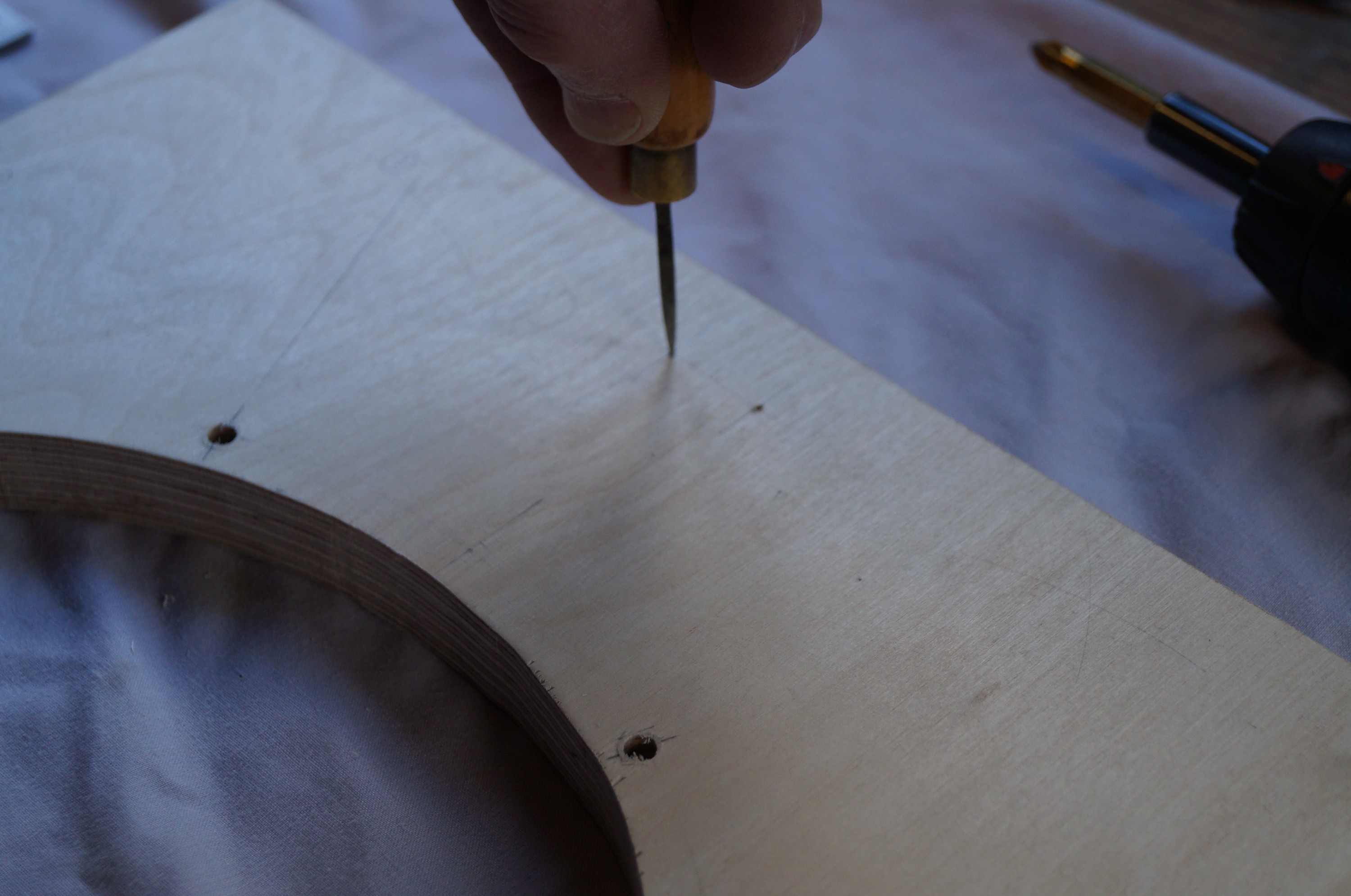
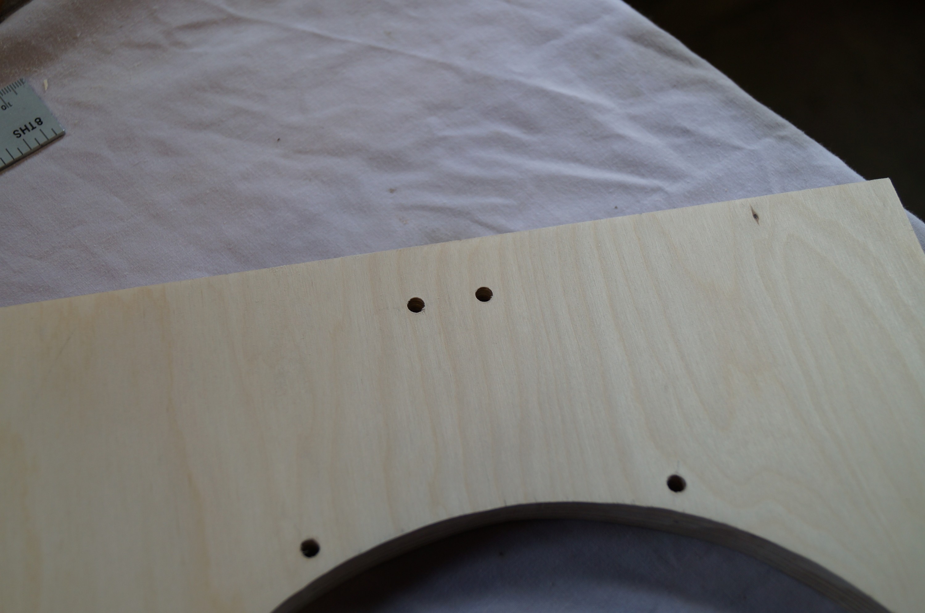
Guide holes before drilling
I therefore decided to ditch the jig for the second box in favour of the more traditional approach – painstaking marking out of dowel positions with a very sharp pencil. At least this could be done in a warm kitchen. For accurately positioned dowels the trick was to use a bradawl to mark each one with a small hole before drilling; this held the drill position well. Tedious but worthwhile; the second woofer box came together almost perfectly with minimal adjustment required.
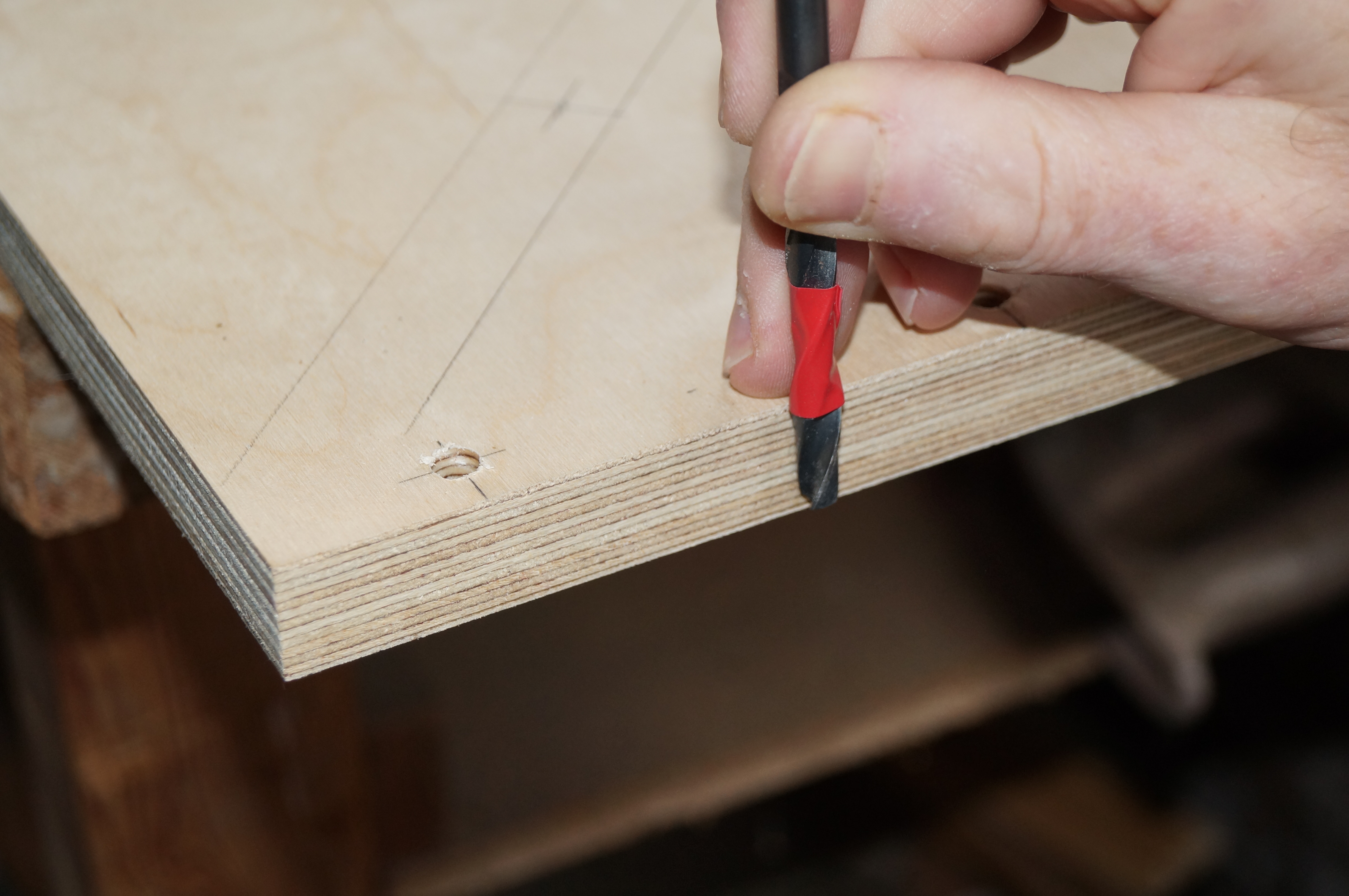
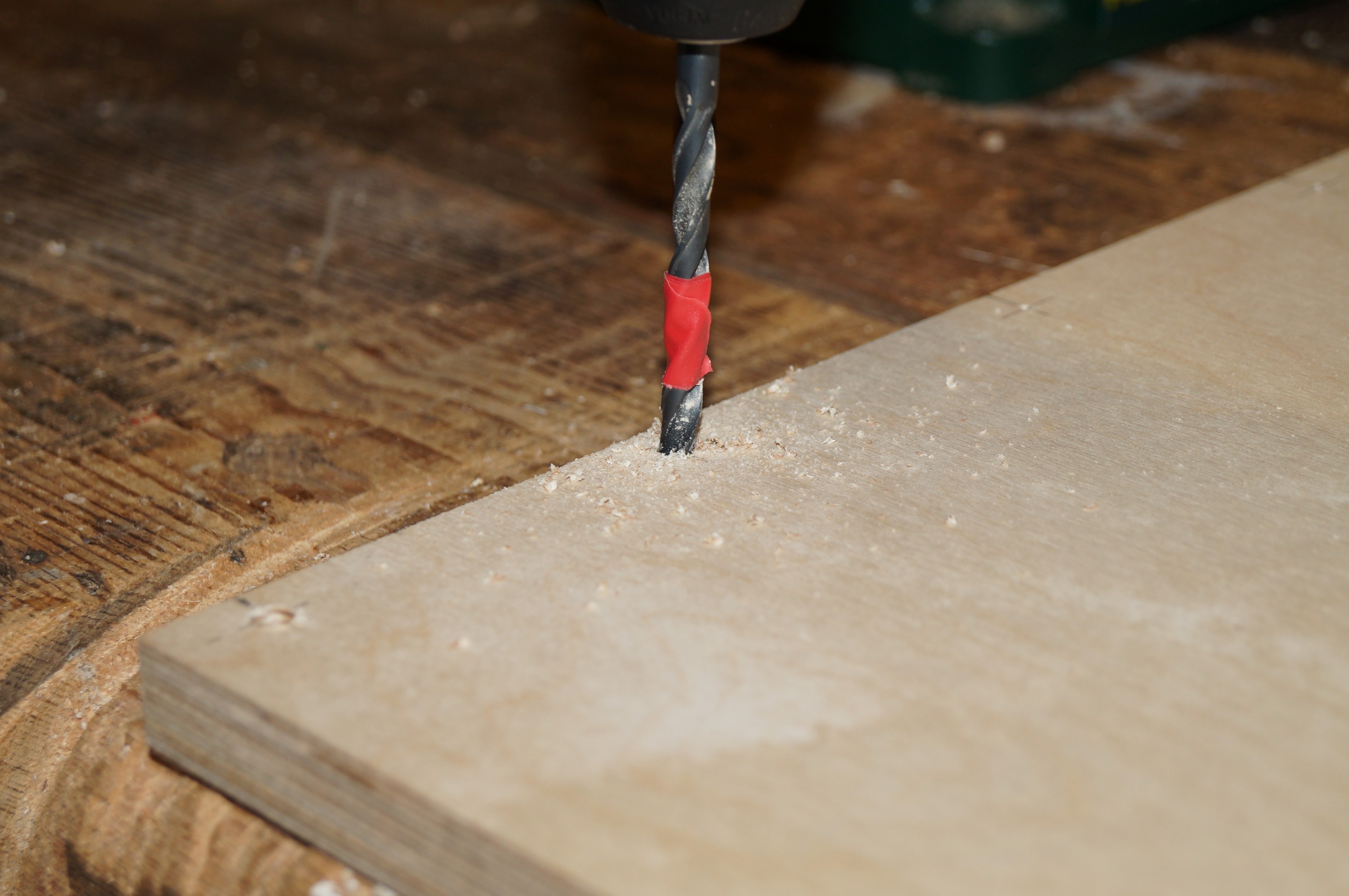
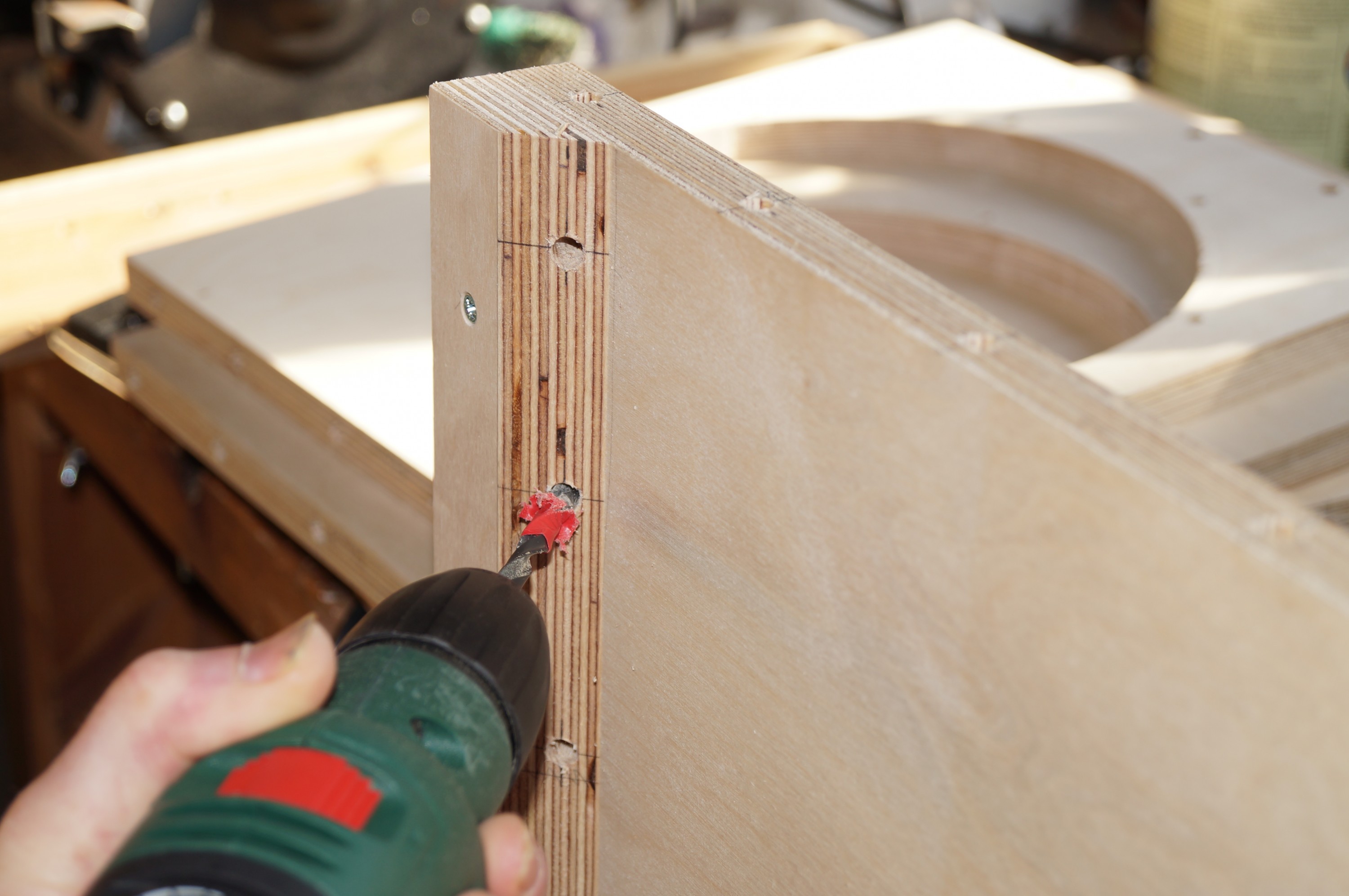
Setting drill depth
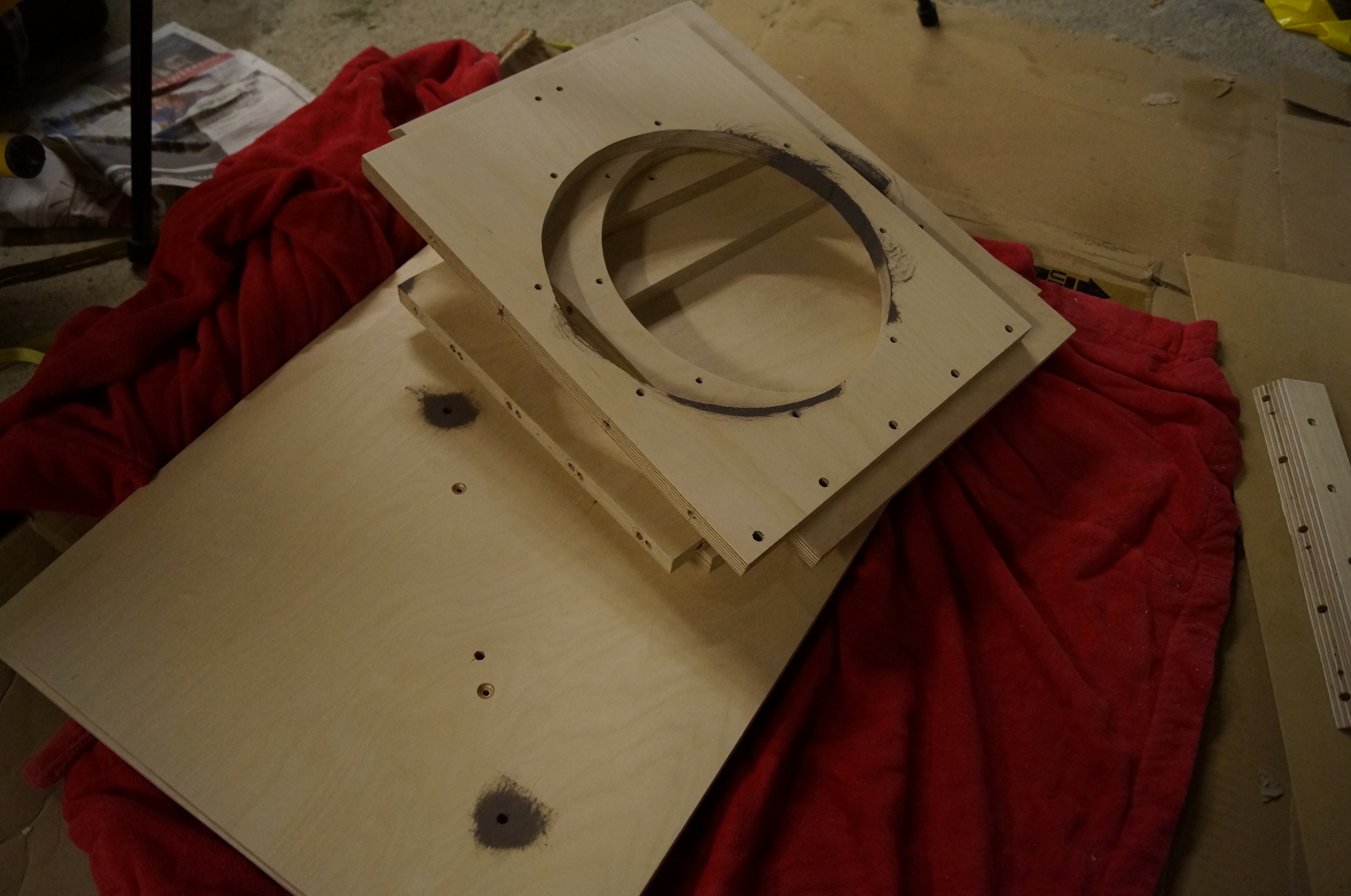
Dowel hole depth is obviously more critical drilling perpendicularly into the flat surfaces. I used insulating tape round the drill bit to mark approximately 15mm. Having smugly taken a photo of this I promptly drilled right through one of the sides – twice! I was rushing, and was drilling too quickly. Ah well, nothing the Toupret filler won’t rectify later (and the sides are hidden by the bridge anyway).
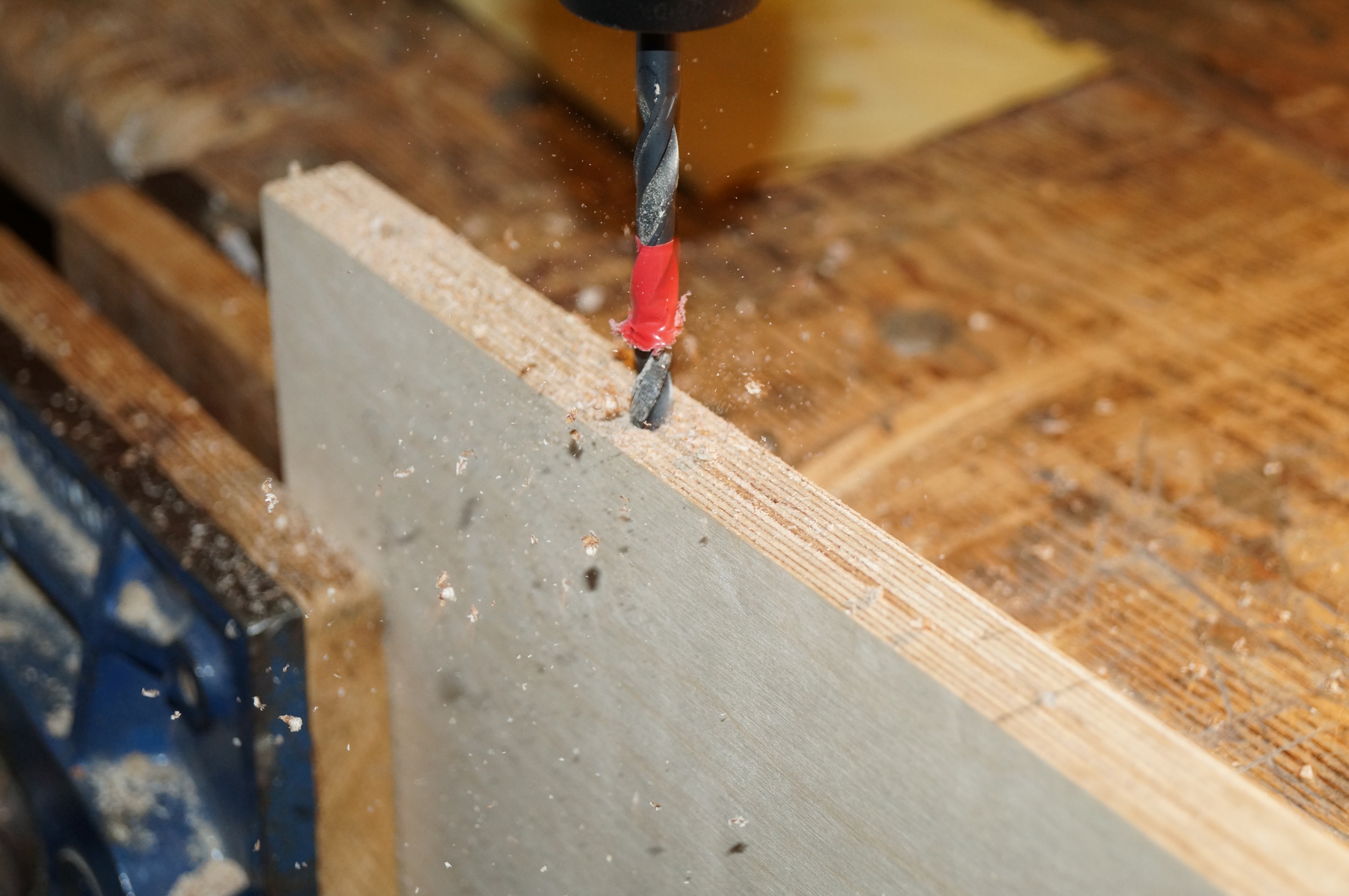
Drilling face holes… and edgesSrew to top and deepen
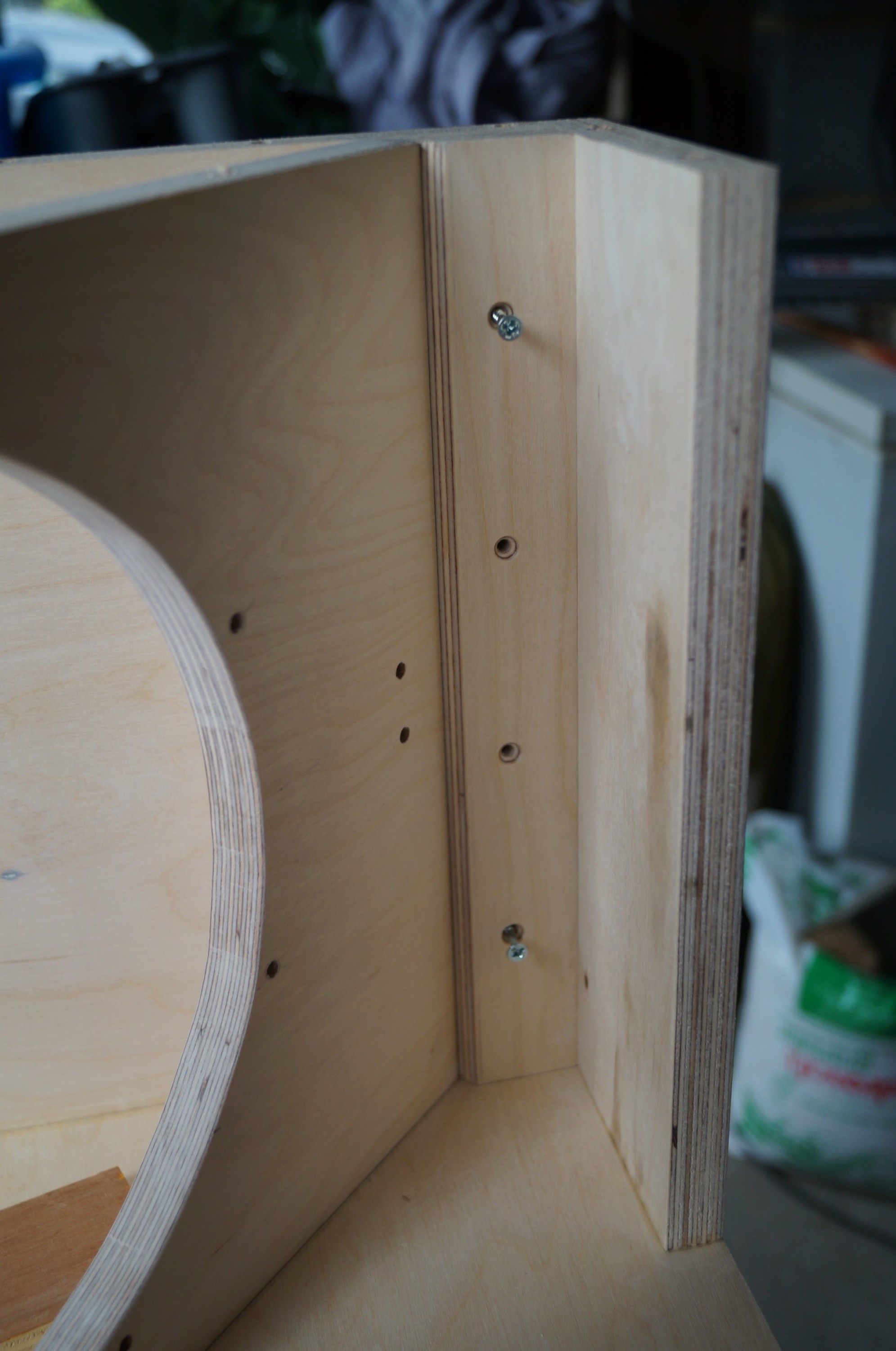
A few photos of construction details.
Apart from those anchoring the V-frames to the sides, screws were used only in hidden areas, namely the filler behind the front flap and the lower V-frame joint with the bottom.
Drilling dowels on the spacer
Drilling dowels for the upper V-frame mitre joint.
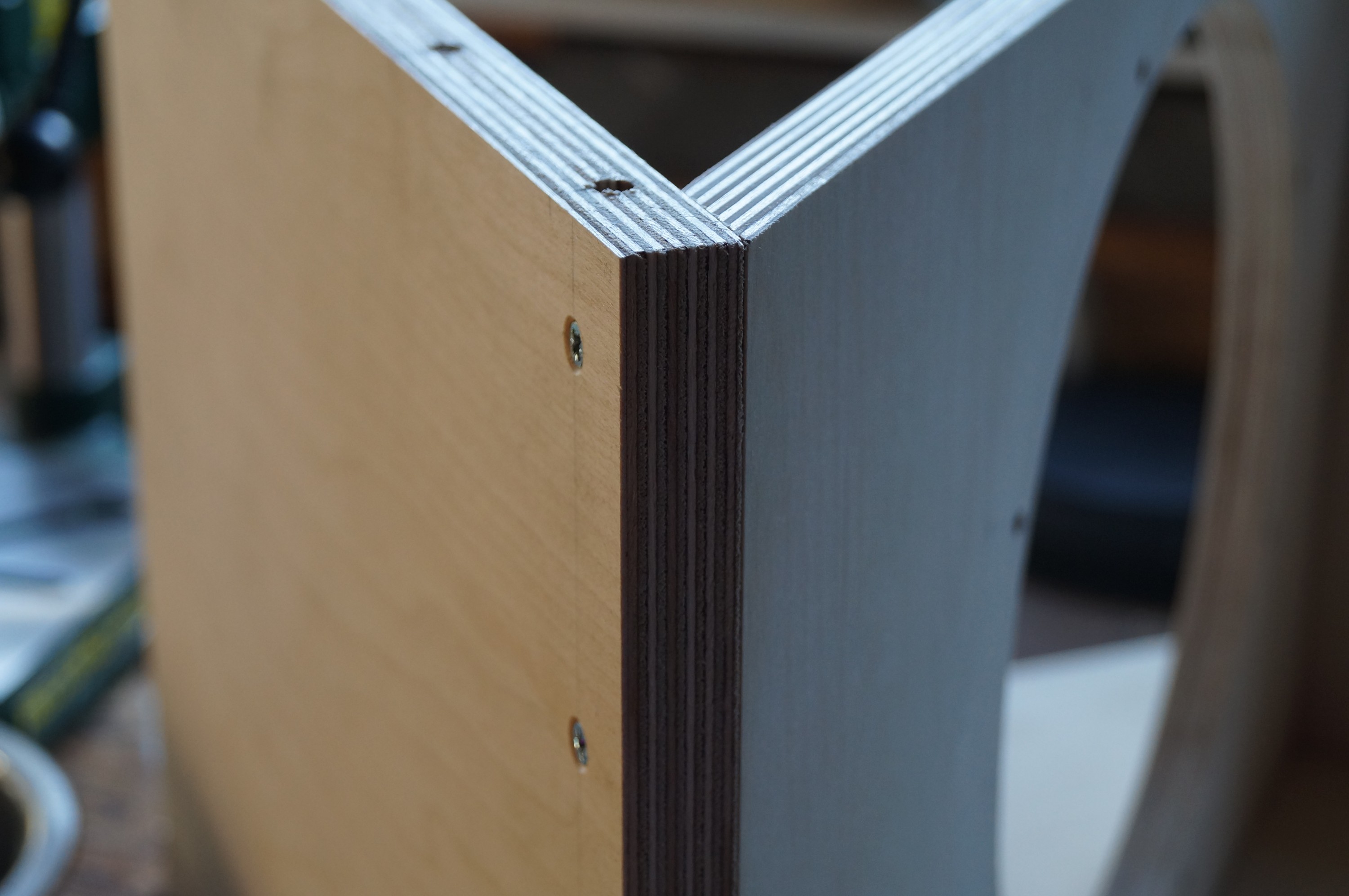
V-frame in positionLower V-frame joint detail
Setting out V-frame and bottom mitre joint. I drilled a 5-dowel joint between upper and lower V-frame elements.
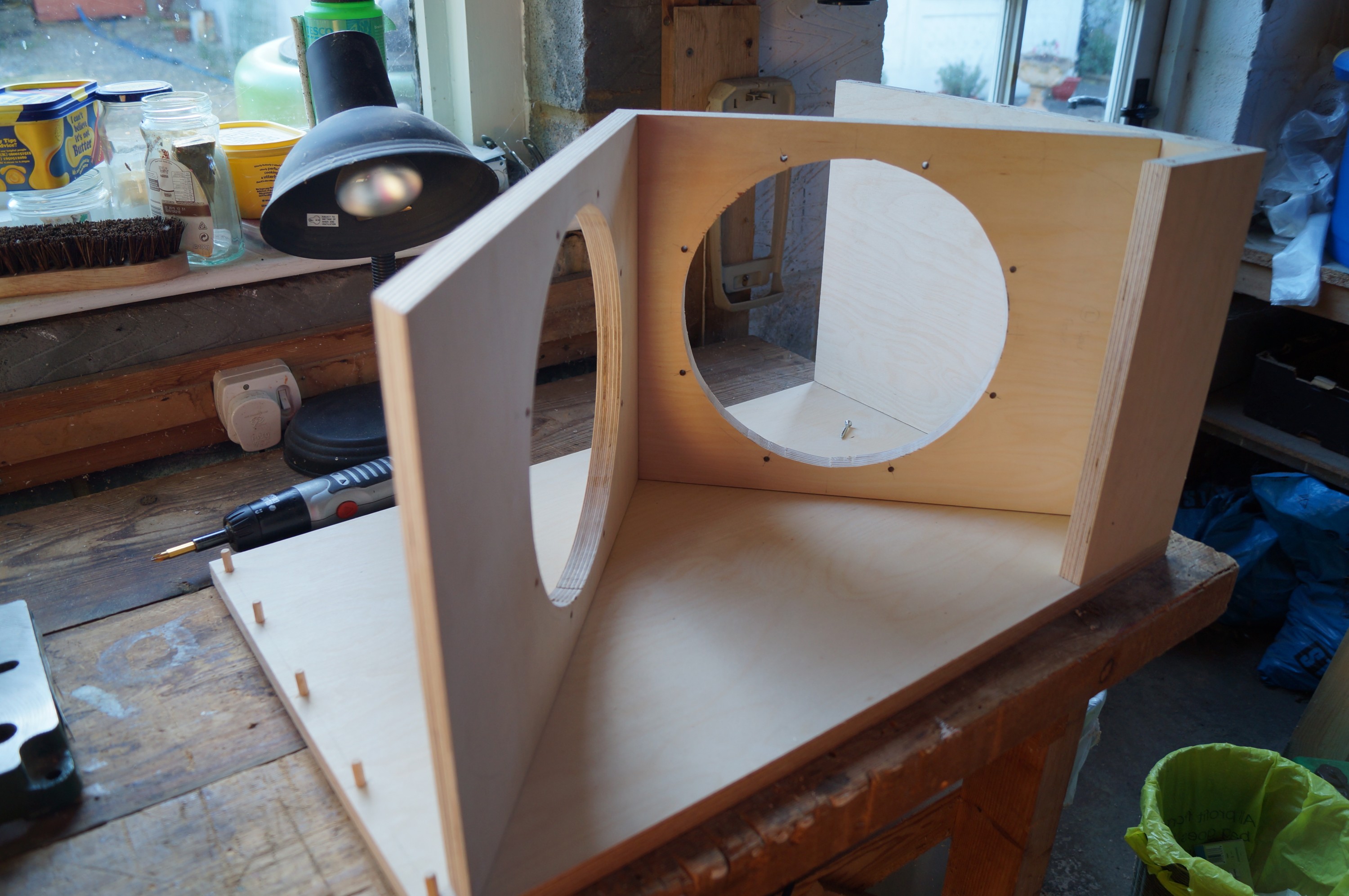
Second side dry fitMarking side dowels
Fitting “top” side before marking out V-frame dowel positions.
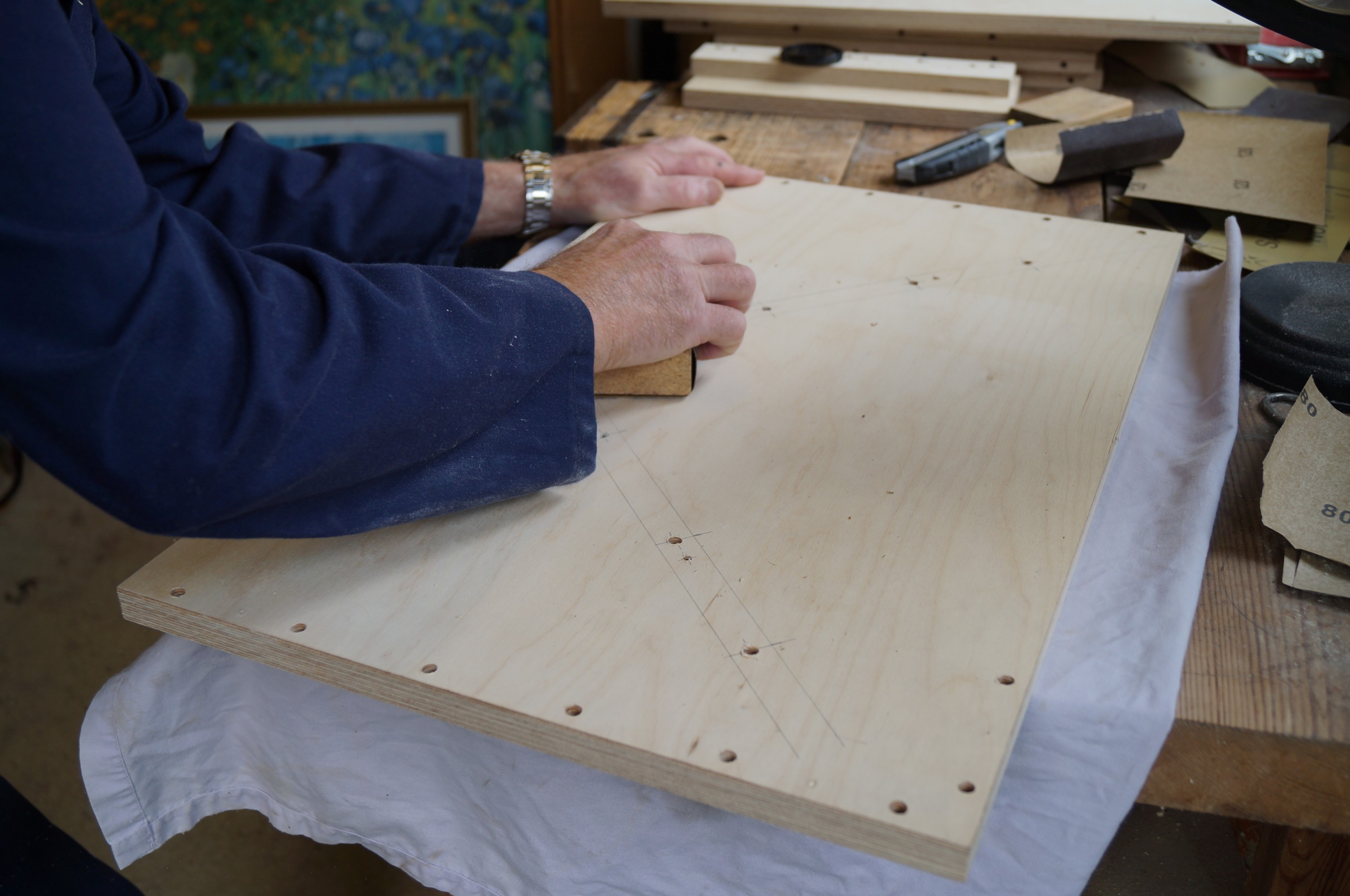
I am impatient to get on with the gluing up, however the advancing years have happily brought reserves of patience I was certainly not in touch with as a younger man. Preparation, preparation! I sanded down all the flat surfaces today, using 80G, then 120G – the nooks and crannies in the completed woofer boxes make this nigh impossible after assembly.
Marking U-W wire holesWill be hidden by front flap
I was pleased that I remembered to drill holes in the upper V frame to take the upper woofer wires through to the rear.
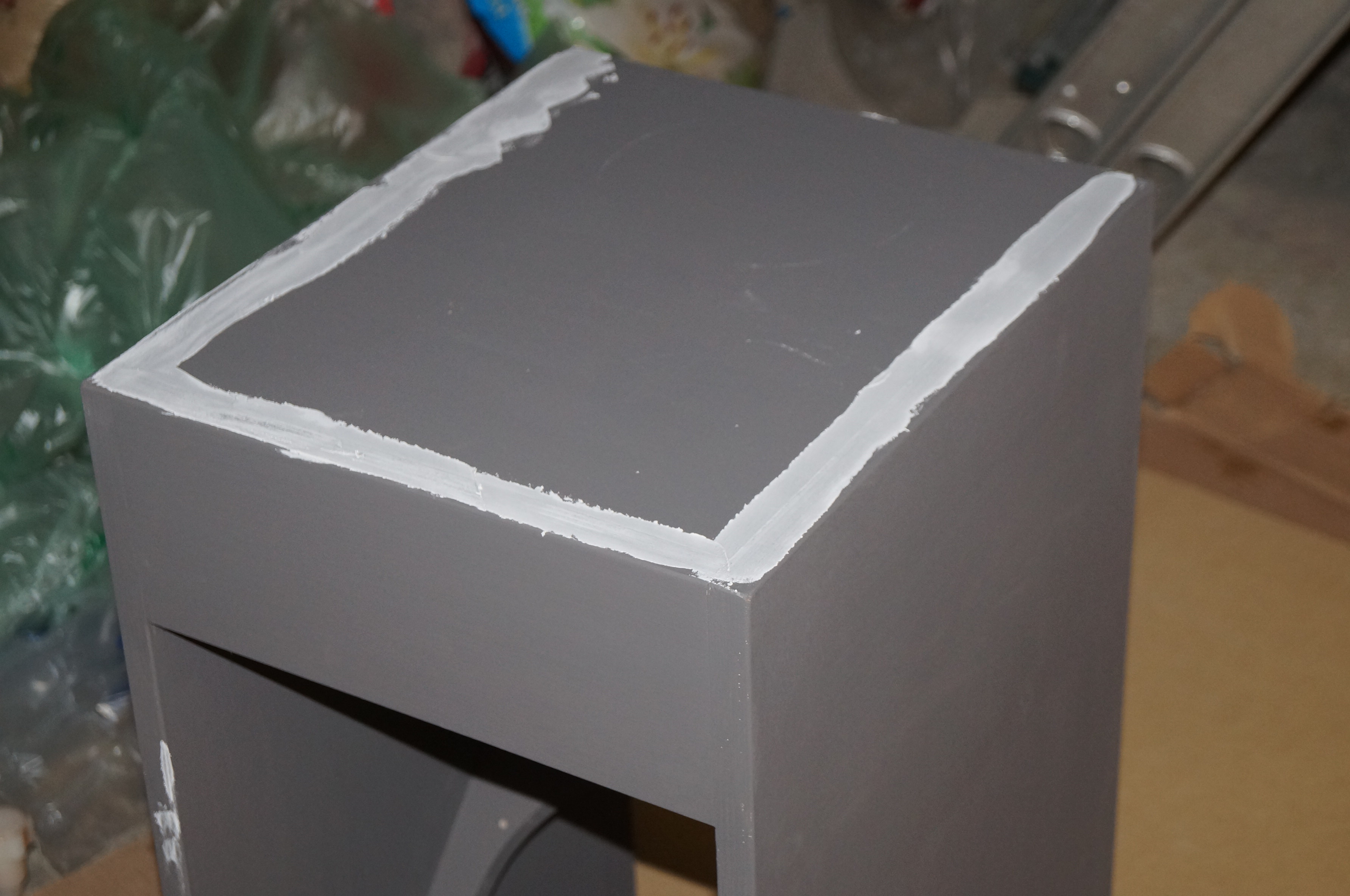
Spot priming done
Last job of the day was spot priming various surface imperfections (and my unintentional through-holes) prior to filling tomorrow. I have decided to make life easy for myself by going the acrylic route, and I’m using Bedec grey primer. I’ve also bought tins of Bedec matt black and satin black top coat as I don’t know which will look best – I can use the same stuff for the tweeter baffles later.
1. Top to front flap, followed by both to side (not shown)2.1 Filler to upper V-frame
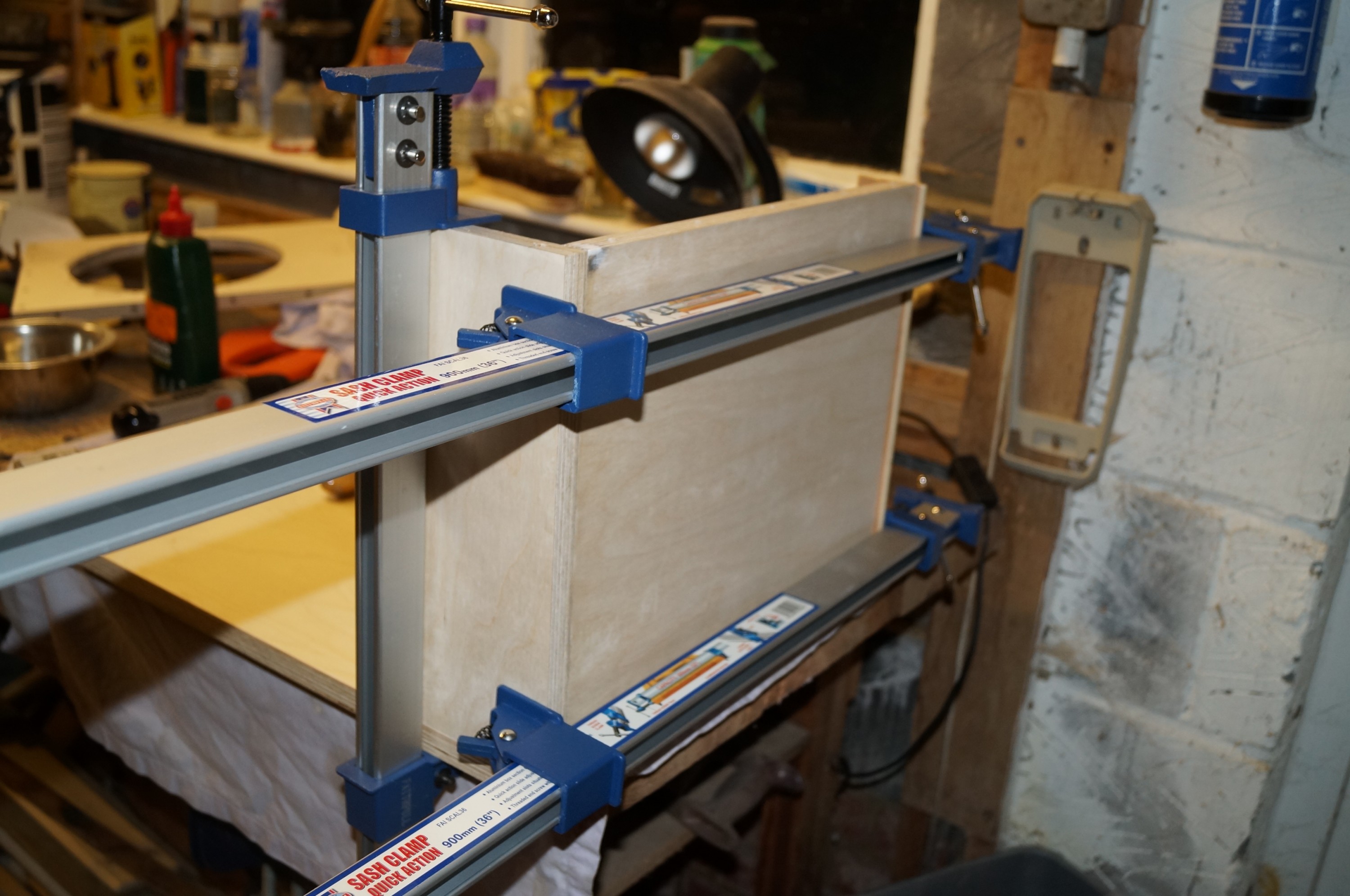
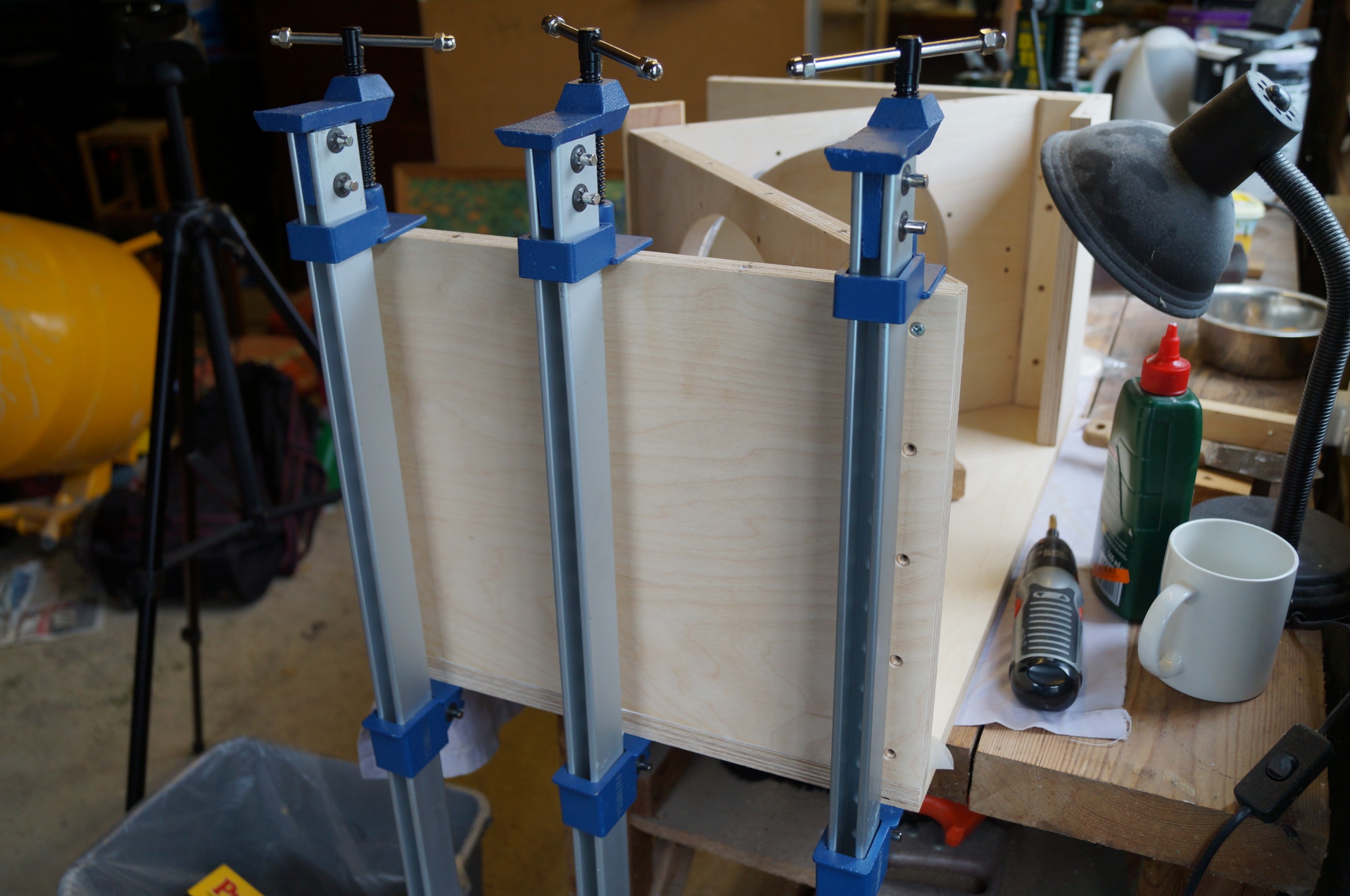
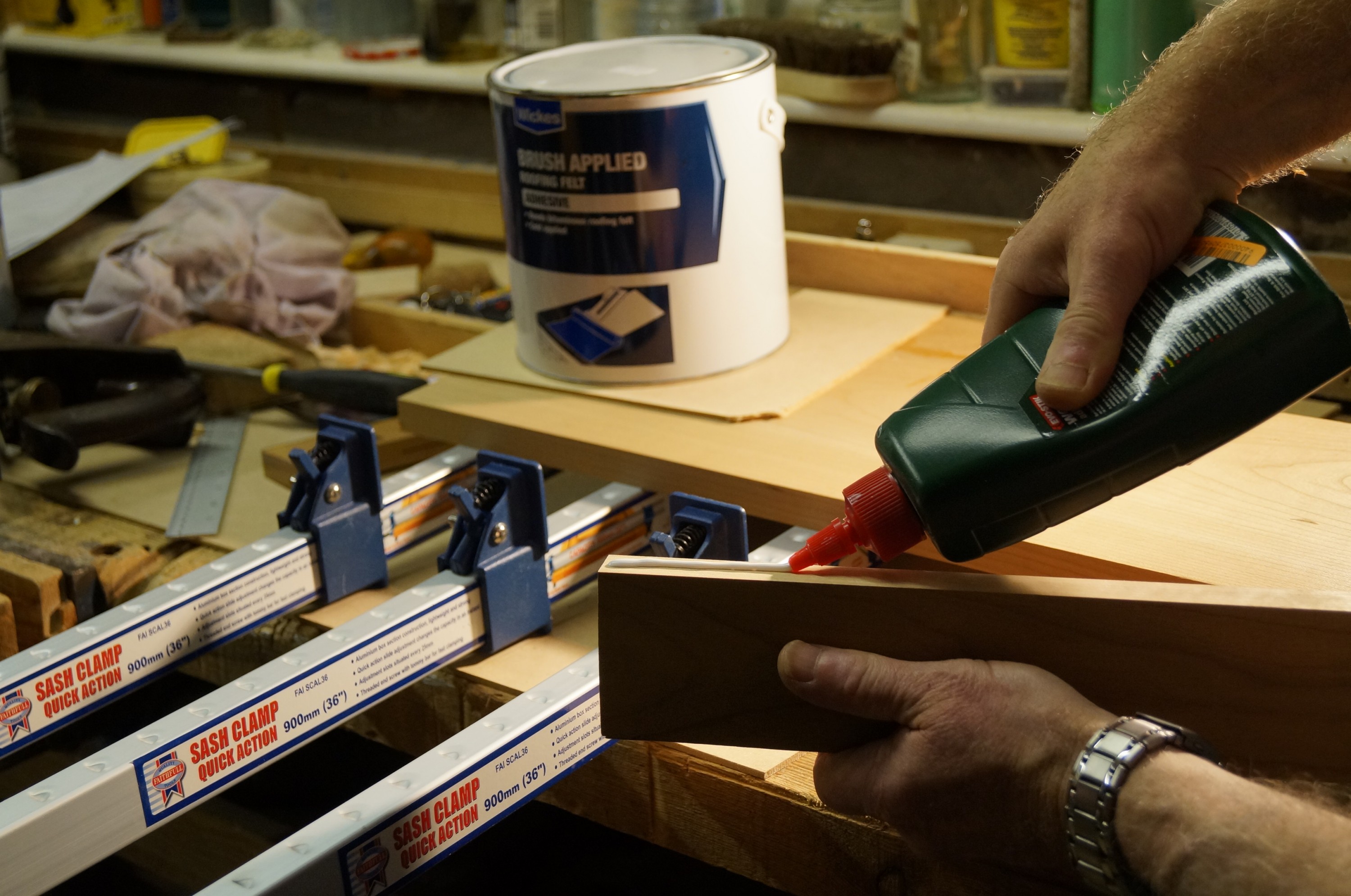
Good progress since last post – both woofer boxes now glued and screwed. The process was not without incident, but no major glitches. I was glad I had invested in some aluminium sash clamps, although soon found myself wishing I had ordered six rather than four.
I knew that order of assembly was important from thinking about this as well as perusing other audiophiles’ build logs (notably Bill Schneider’s meticulous record). Using dowels to strengthen the joints between the V-frame and the sides makes assembly order critical, as all V-frame elements have to be assembled and glued before lowering these onto the side dowels. The photos show the order I adopted.
When assembling the first box I discovered (after priming dowel holes with glue!) that the slightly proud through-dowels between the upper V-frame and the small filler behind the front flap prevented me from dropping the V-frame assembly in place! – I had anticipated sufficient play to allow this, but no…
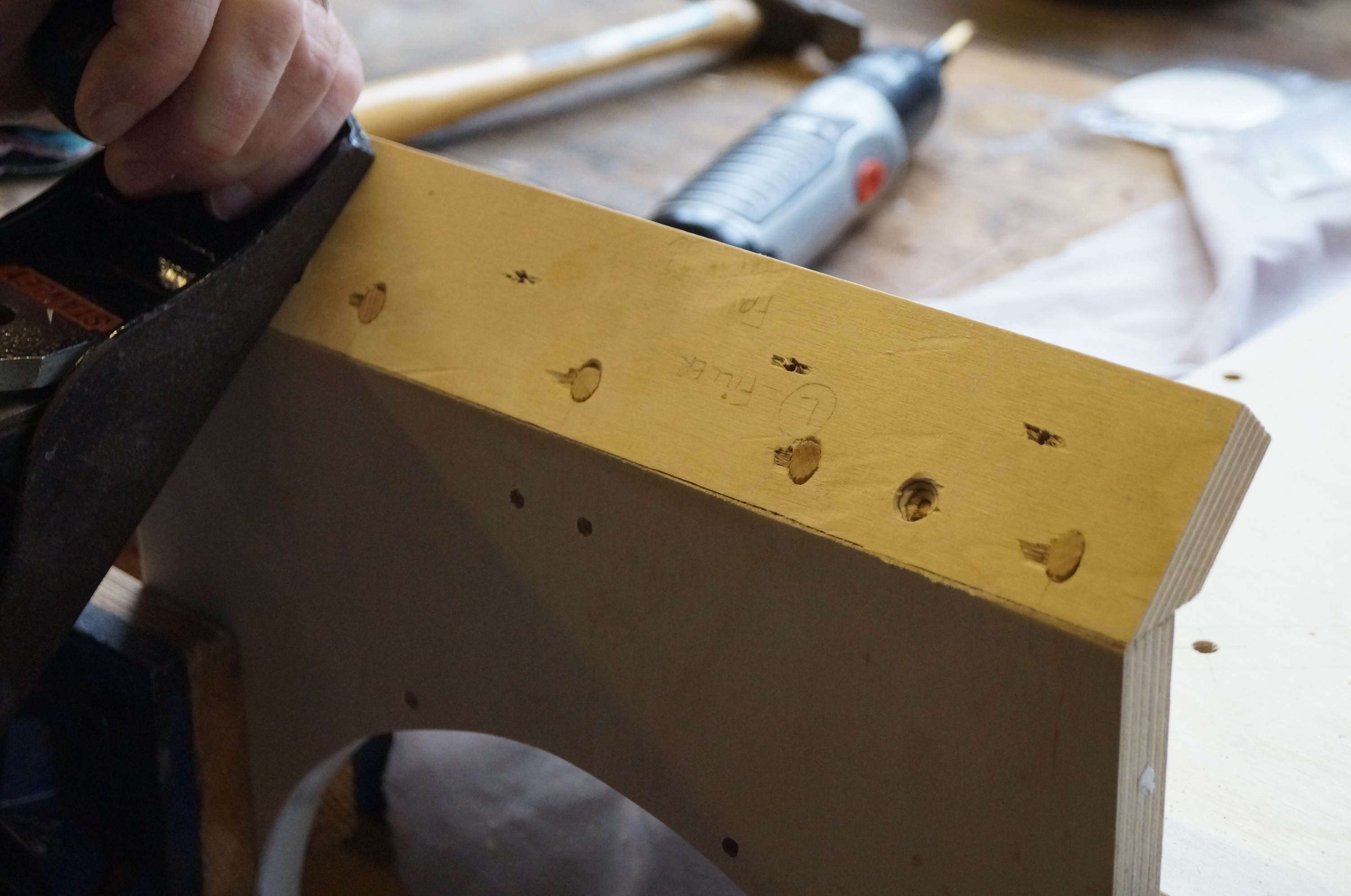
2.2 Planing off protruding dowels
Some rapid planing off of the protruding dowel ends rectified the problem. This apart,assembly proceeded uneventfully.
3. Upper to lower V-frame (located on dry side dowels)
4.1 Bottom to side (dry-screwed to lower V-frame)
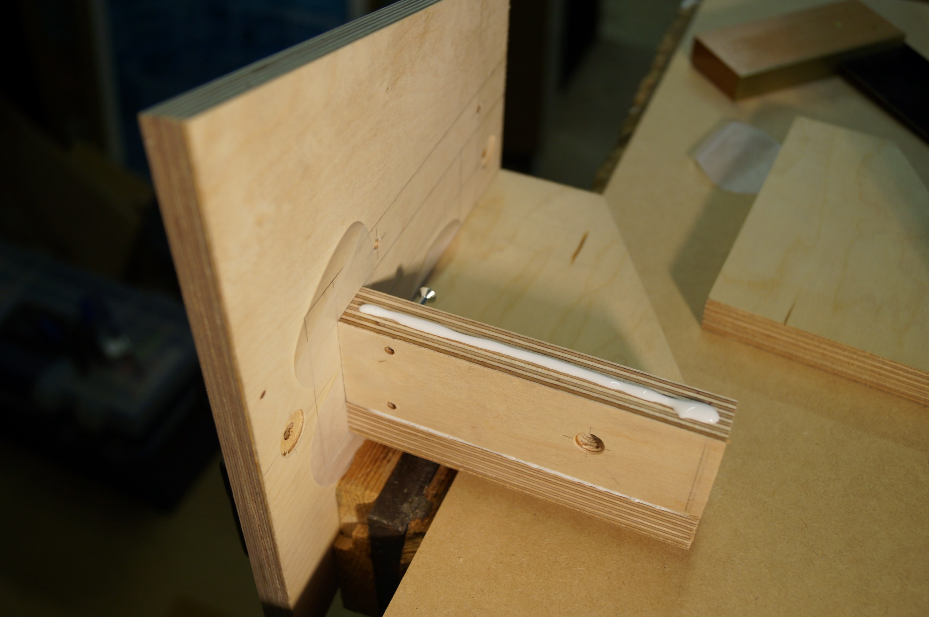
4.2 Wax disc to keep glue from dry joint
I used waxed discs (as used for preserves) to confine the Evostick to the joint being glued during the staged assembly; another good idea from Bill Schneider.
5. V-frame assembly lifted out before gluing up side dowel joints
The dowel-glued V-frame assembly, shown separately here, felt extremely strong with minimal give – I was glad I had decided to glue it in place using the side dowels to ensure correct alignment. Its stiffness was what led to my protruding dowel problem!
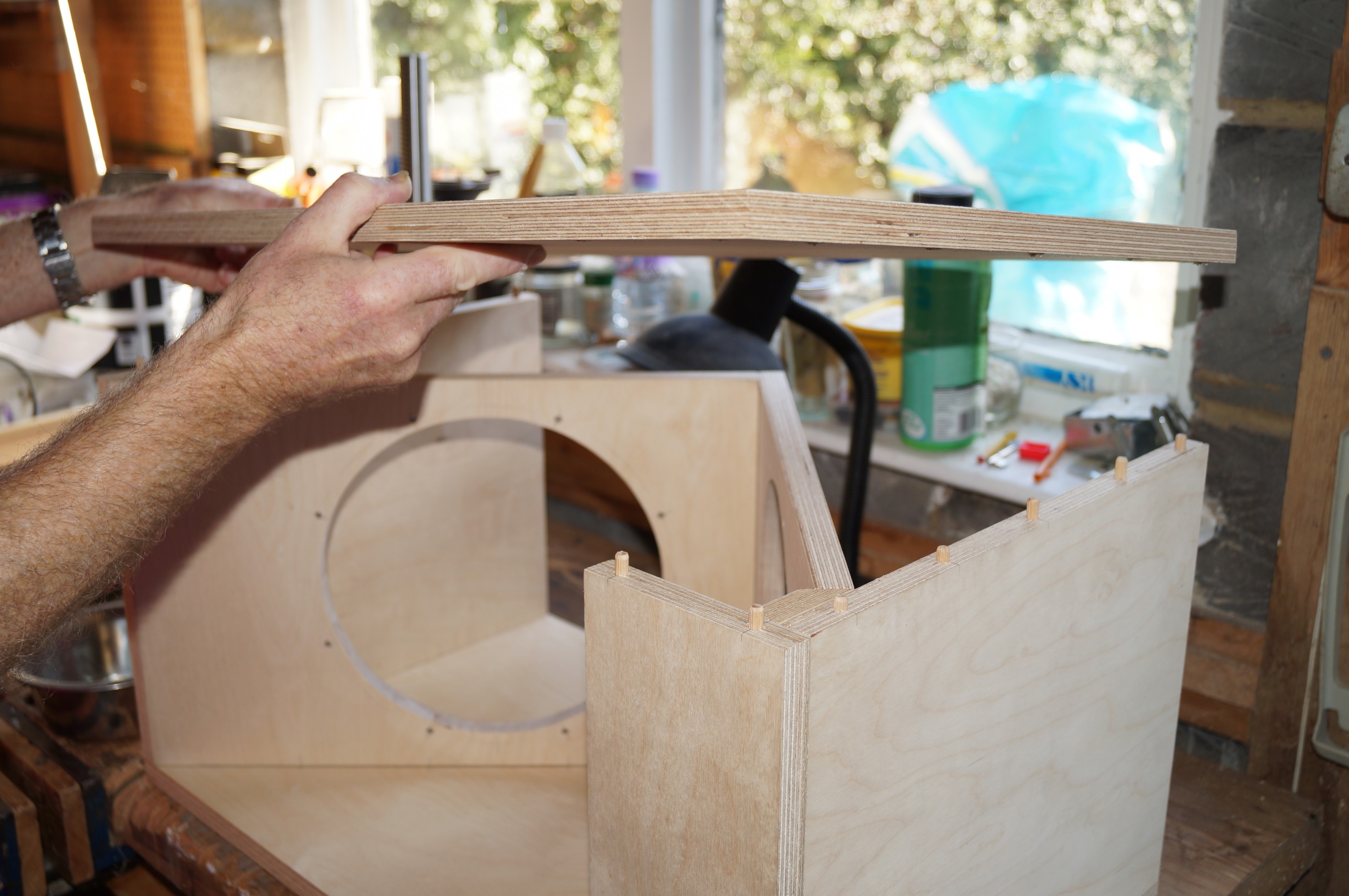
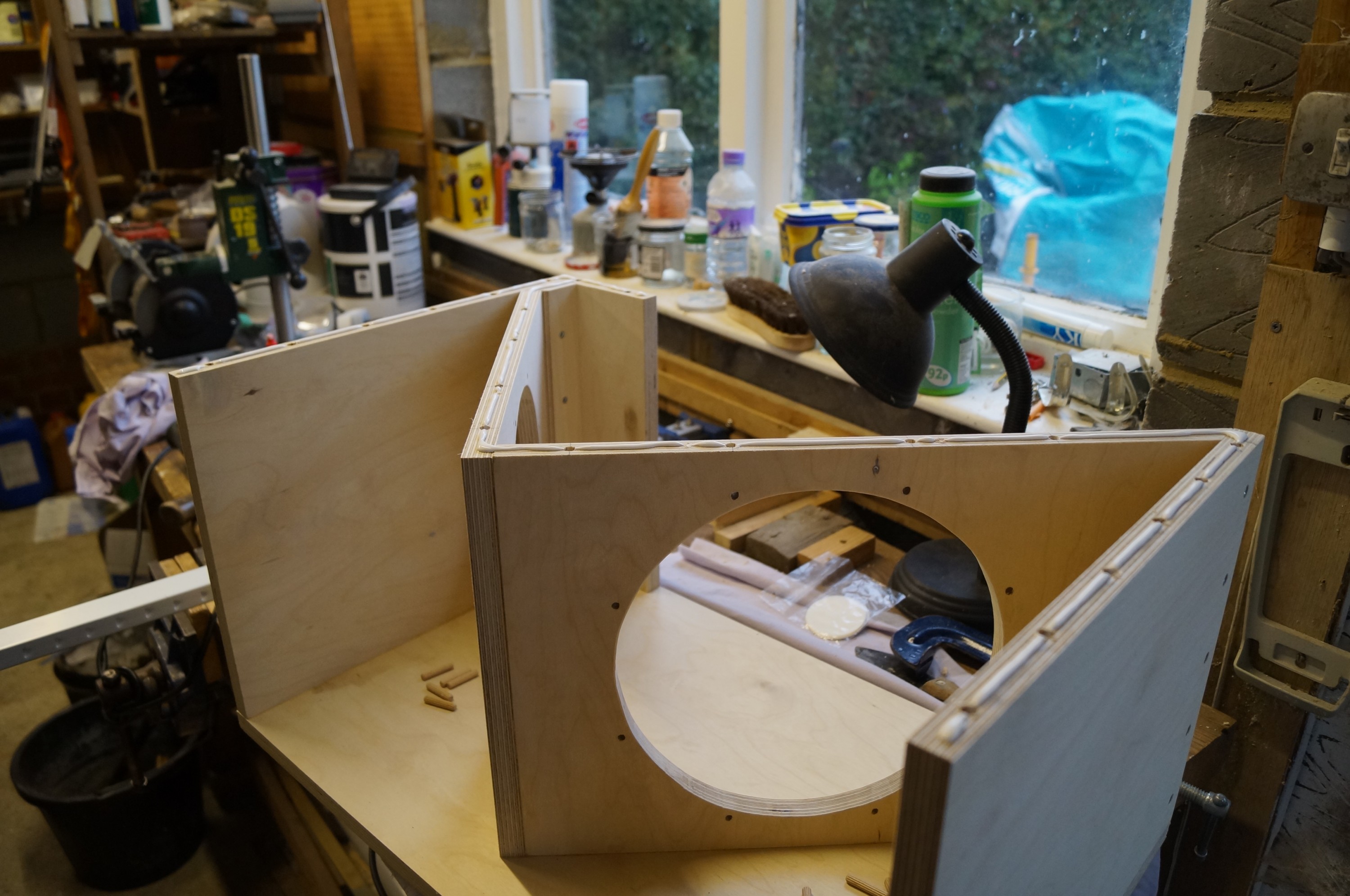
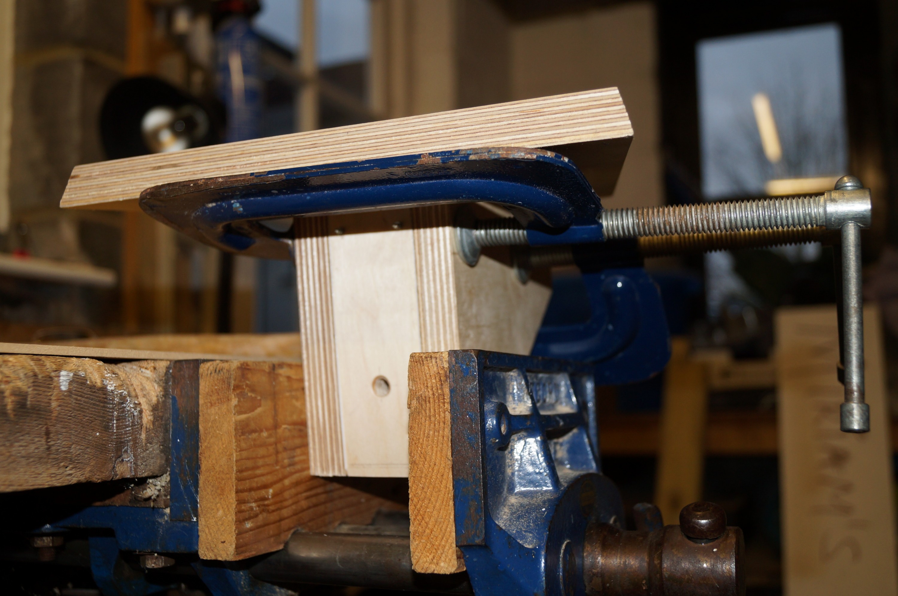
6. Checking fit and assembly before gluing and screwing V-frame in place
This shows the underside of the front flap and mitred filler piece; I used screws here (impossible to clamp), and I won’t be filling these in their concealed position.
7. One side done; gluing up for other side
The boxes came together reasonably well and square; the 2″ x 8 screws countersunk into the sides pulled the V-frame side joints nice and tight.
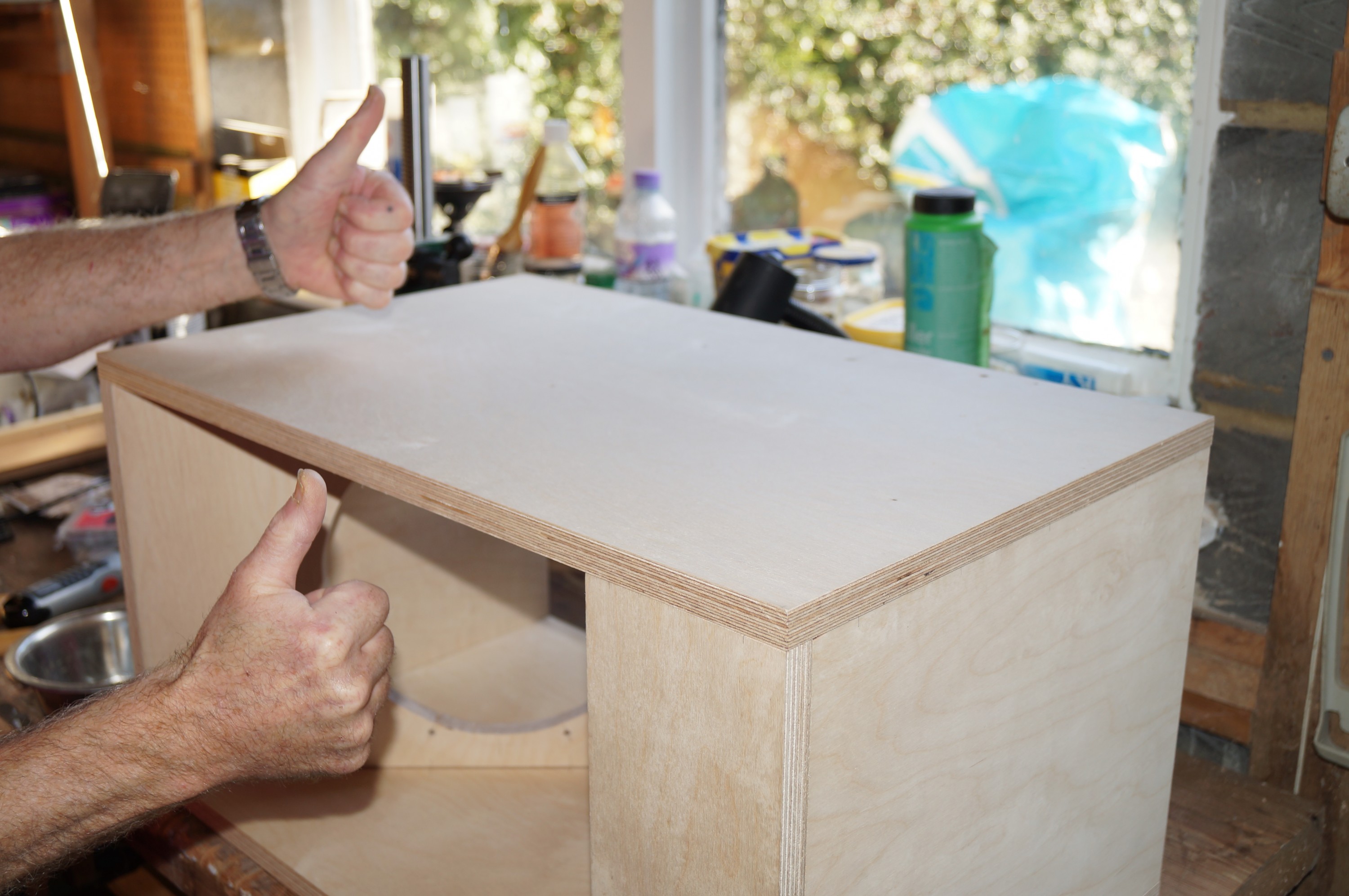
8. Second side glued and screwed – assembly complete!
Some planing was needed to top and bottom to bring sides flush before final sanding. I did have to fill the front flap on one box as the lower edge ended up a millimetre displaced backwards. I spot primed these areas together with all countersinking and other minor surface defects before filling.
I had researched wood fillers before commencing the build, and had settled on Toupret TX110 filler (the French like to finish stuff properly). It needs a few hours to develop full strength but it cures very solidly and sands beautifully flat thereafter – a good buy. Filling and sanding the countersinking on the sides and bottom completed the making good.
In the last week or so the boring work of priming, sanding and filling the woofer boxes has got under way, although the tedium is relieved from time to time by researching and ordering miscellaneous items from the internet. Chemical black bolts and self tapping screws of varying types from Accuscrews to mount the drive units and tweeter baffles, brass inserts and black flat topped bolts from Insert Co (UK) Ltd for the baffle brackets, a counterbore for the inserts, and finally Neutrik Speakon connectors (4-way for woofers, 8-way for the mid-range / tweeter baffles) from Canford.
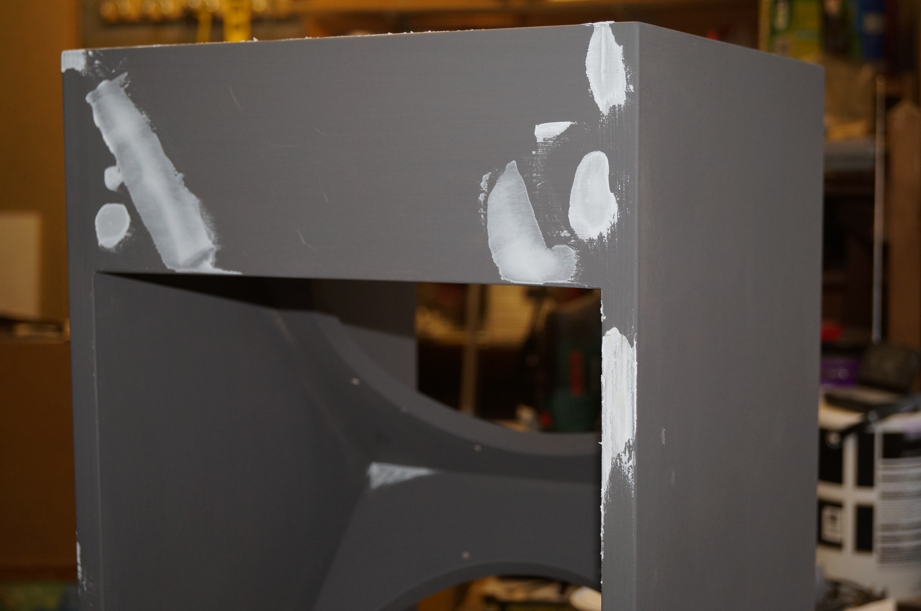
First full primer coatFilling, filling…
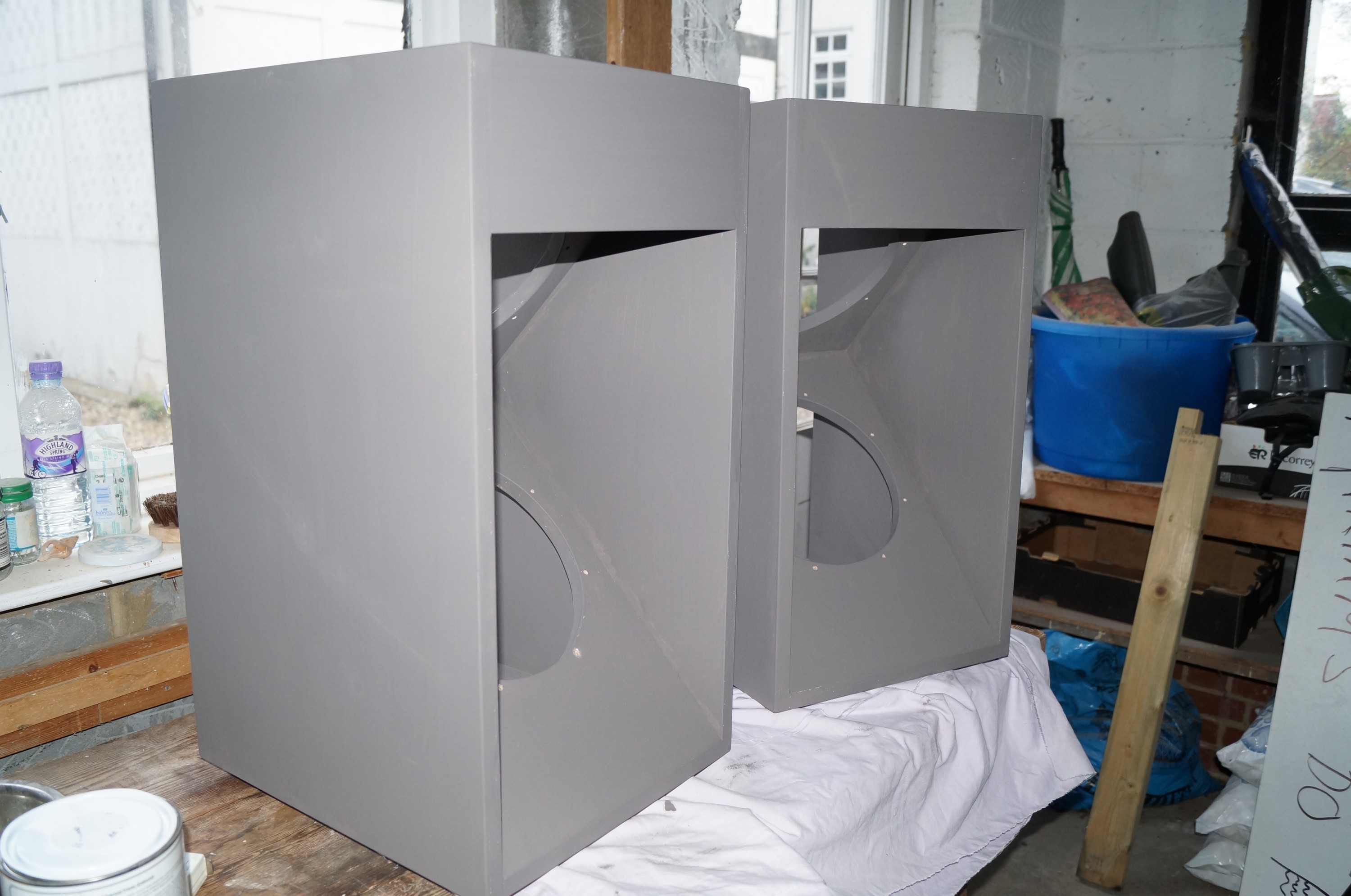
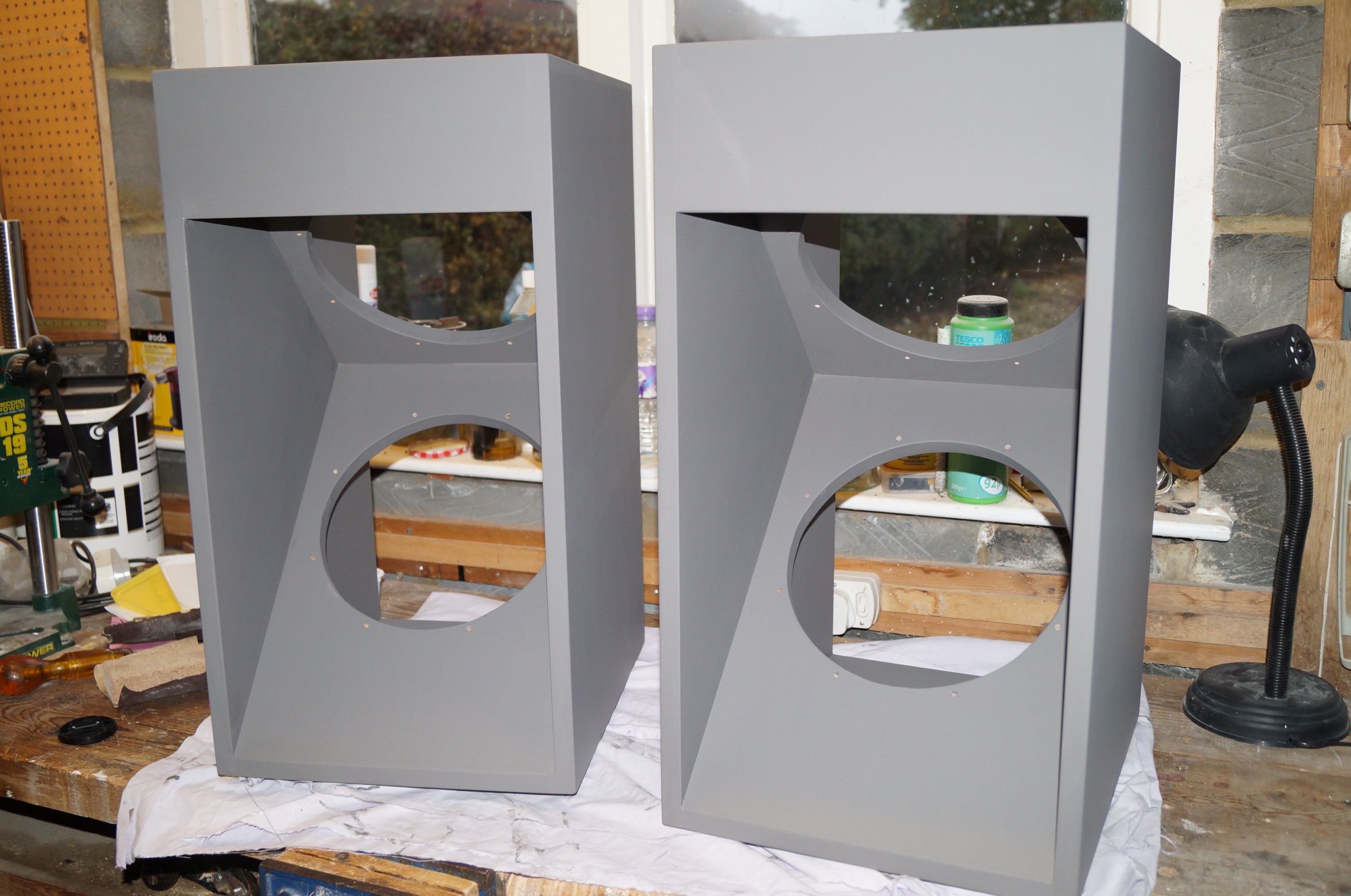
The woofer boxes have now had their second full primer coat, and are looking good, if somewhat sinister. Wood grain is still visible, mainly where end grain is to be found, but they are feeling very smooth already. I’m leaving them at this stage to turn attention to the baffle bracket assemblies to which I have been giving considerable thought. The main question was how to build in tilt and toe-in facility without spoiling the overall appearance or involving unduly complicated engineering. My listening chair is quite low so I felt the tilt was essential, and from reading SL’s comments and related links I learned that being able to toe-in the baffles was important for not only minimising side and back wall reflections but also widening the stereo “sweet spot” (two or more listeners).
For tilt I finally opted for fitting a butt-hinge concealed just behind the bottom of the baffle, controlled by a fifth M6 recessed flat-headed bolt engaging in an extra brass insert positioned from the front of the hinged element. I’ll only need a few degrees of tilt so am hoping this will work.
…After second primer coat
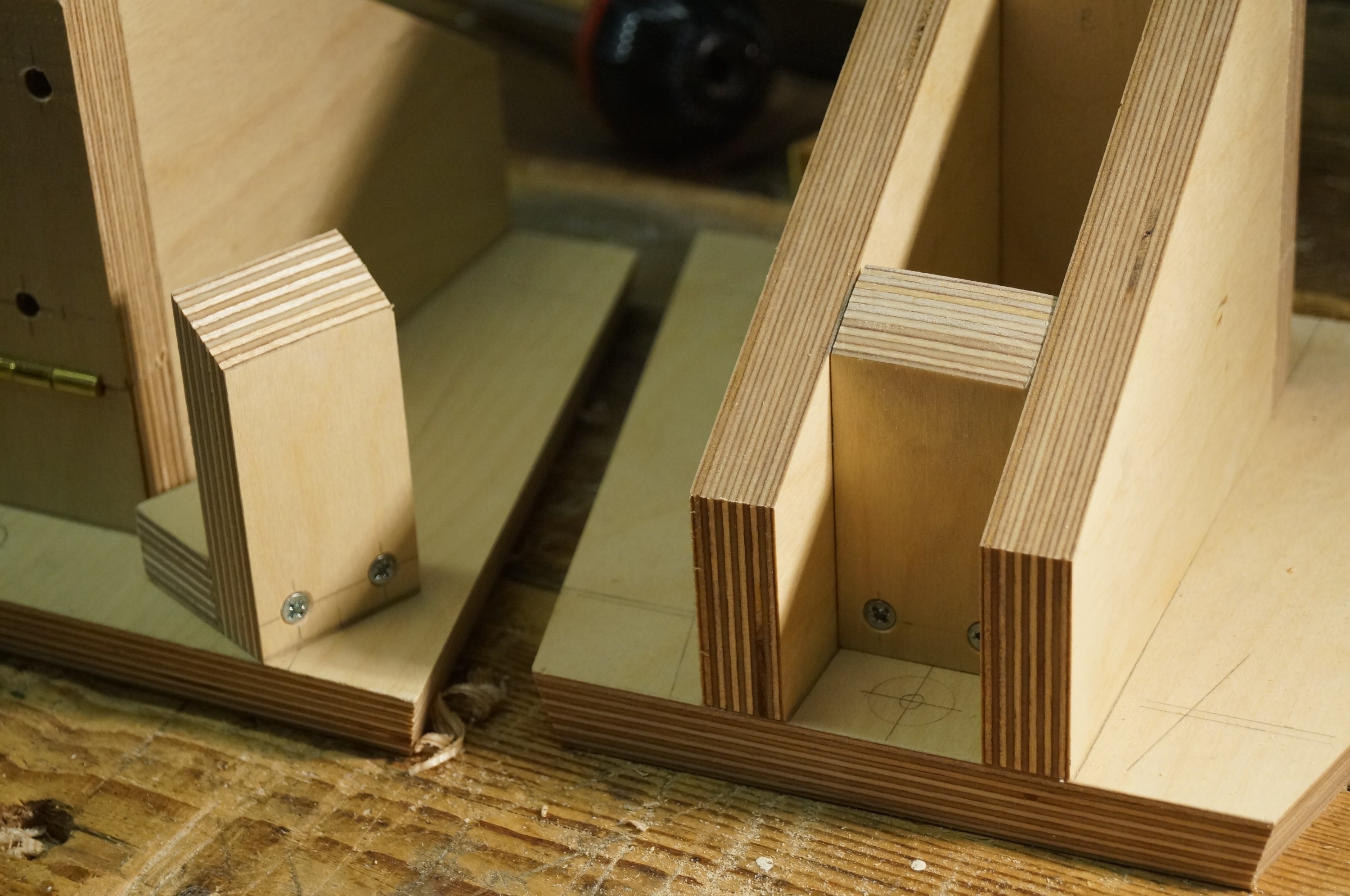
This idea requires some modifications to SL’s basic design, principally the fitting of an additional fixed piece of 18mm ply behind the bracket front through which the adjuster bolt runs. In addition, I need to add a 3mm hardboard spacer behind the baffle for the twin purposes of ensuring (a) the baffle clears the hinge butt (I’m not digging holes in my nice cherry!) and (b) the bottom edge of the baffle won’t foul the front of the bracket when tilted. Finally I am adding a simple bracket inside the back of the support to mount the Speakon 8-way panel connector (6 will be used as with the Mini DSP option the lower and upper midrange units and tweeters are all driven separately).
Toe-in was more problematic. Pivoting the baffle support round a central bolt at the front of the support, vertically in line with the baffle, is easy enough; the problem was what to do at the back of the support. With the baffles tilted downwards I was concerned that the centre of gravity would be thrown forward sufficiently to make a rear bolt through to the bridge from the back of the support essential. I considered cutting a continuous radial slot in the bridge, but felt this would be impractical without a router. In the end I settled for drilling four additional holes, with brass inserts, in the bridge to give 10, 15, 20 and 25deg toe-in. If finer adjustment is needed (which I doubt) I’ll just lug the woofers around a bit…
Finally I ordered four veneered and edged cherry panels from SL Hardwoods for the sides of the bridges. The top and feet will be solid cherry; I have enough of the 7″ by 3/4″ cherry board (for the baffles; also from SL Hardwoods) left, though some jointing up will be required.
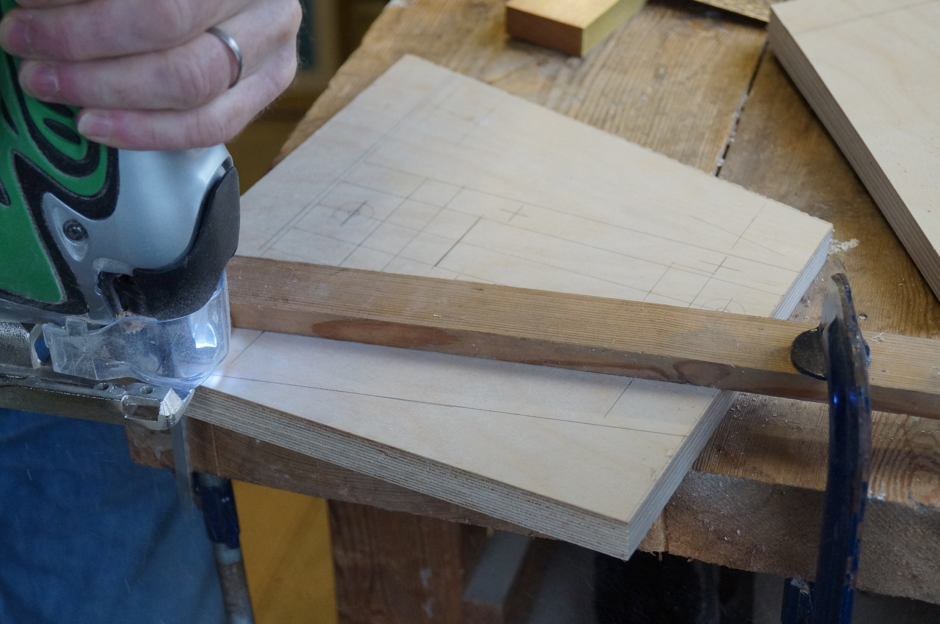
The last week has seen the sometimes fiddly job of marking, cutting and drilling the baffle support parts. My new jig saw came in very useful here. We have a love-hate relationship; I never find it easy to cut accurately to a line with jigsaws, so experimented with running straight cuts using a guide batten clamped to the work – better, though still not reliable enough to cut really close. Leave a millimetre or so and plane therefore.
Front hinge assembly
The first fiddly job was cutting the hinge rebates for the front tilt assembly. Birch ply is solid stuff! – so chisels were thoroughly sharpened first. One side was perfect first time; on the other the tilting upper part was a little out of line, requiring a few tho’ off to deepen the rebate at one end.
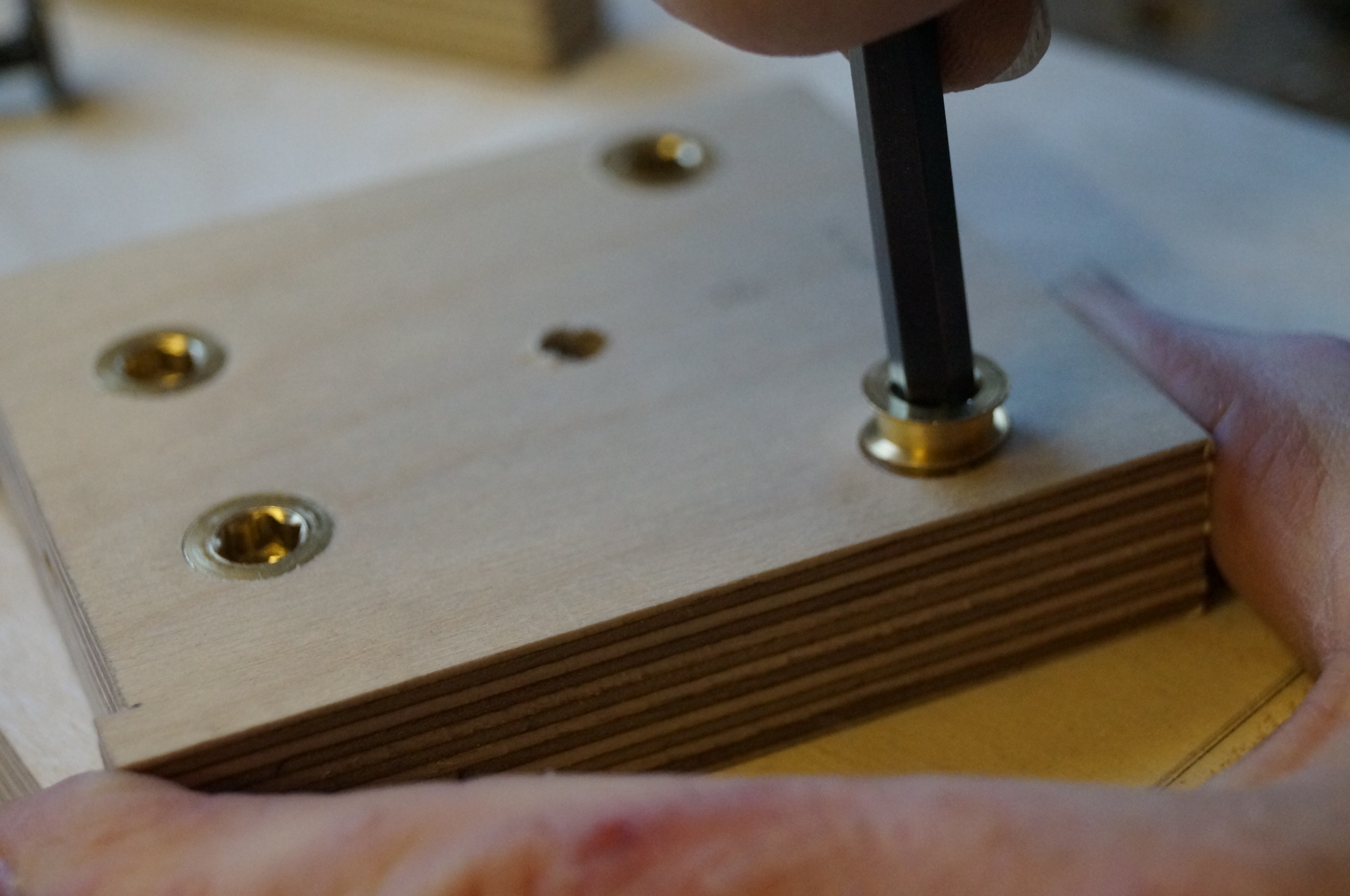
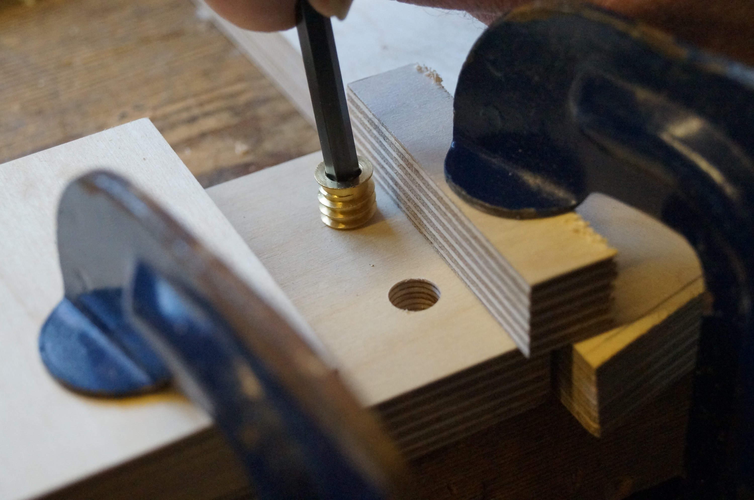
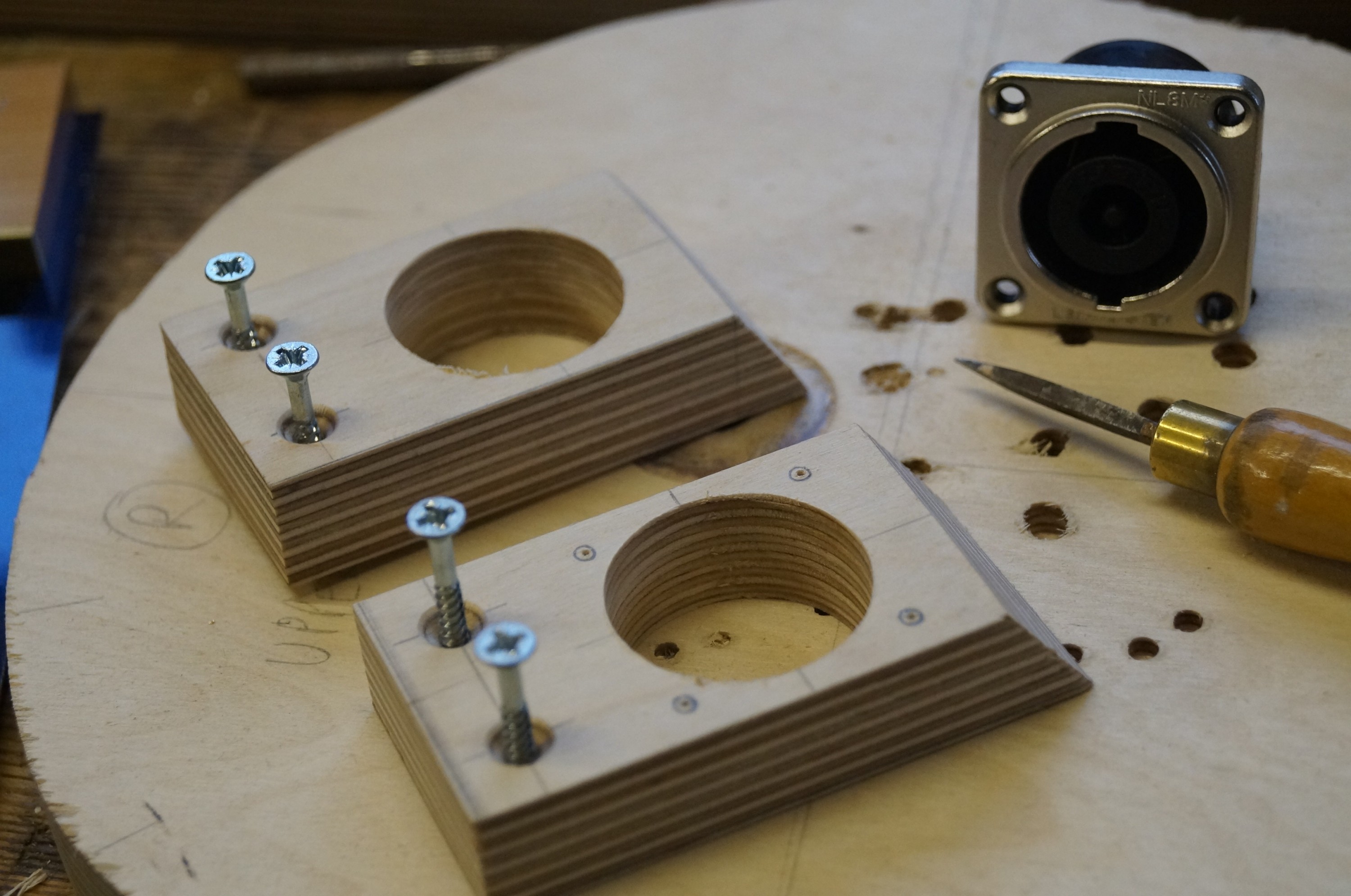
Fitting the insertsProtecting against splintering
The other “learning experience” was setting in the threaded M6 brass inserts. My counterbore diameter was 10mm – the manufacturer specifies a hole between 10 and 10.8mm diameter so the inserts were tight. They are difficult to screw in accurately vertically and require regular adjusting heaves on the hex spanner to correct wander every turn or so. In the process there is a tendency for the outer plywood layer to lift and splinter, so I clamped scrap blocks either side after the first attempt. I then had to remove the inserts to widen the guide hole out to take the bolts before final insertion. Not all were perfect… but good enough.
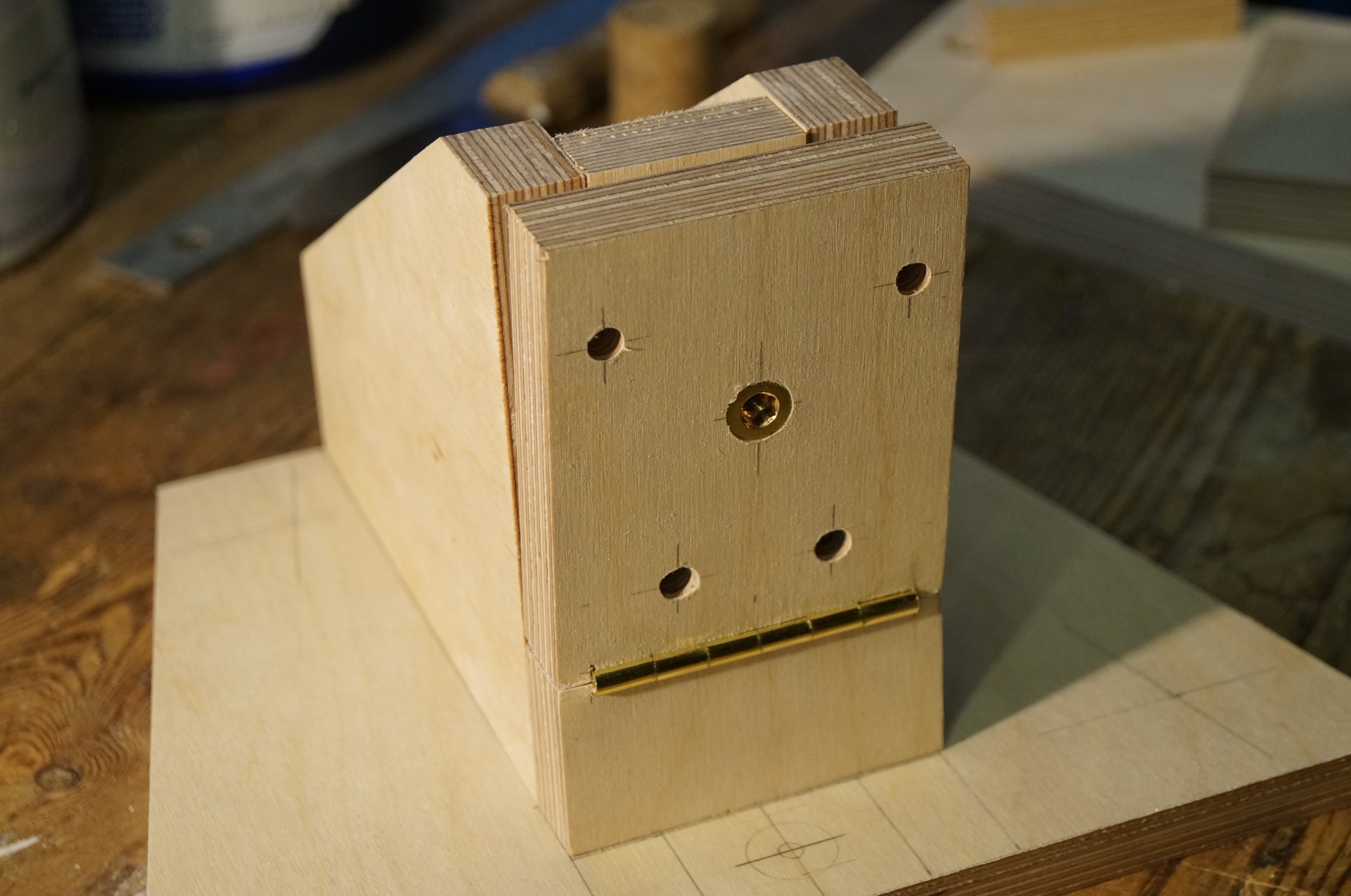
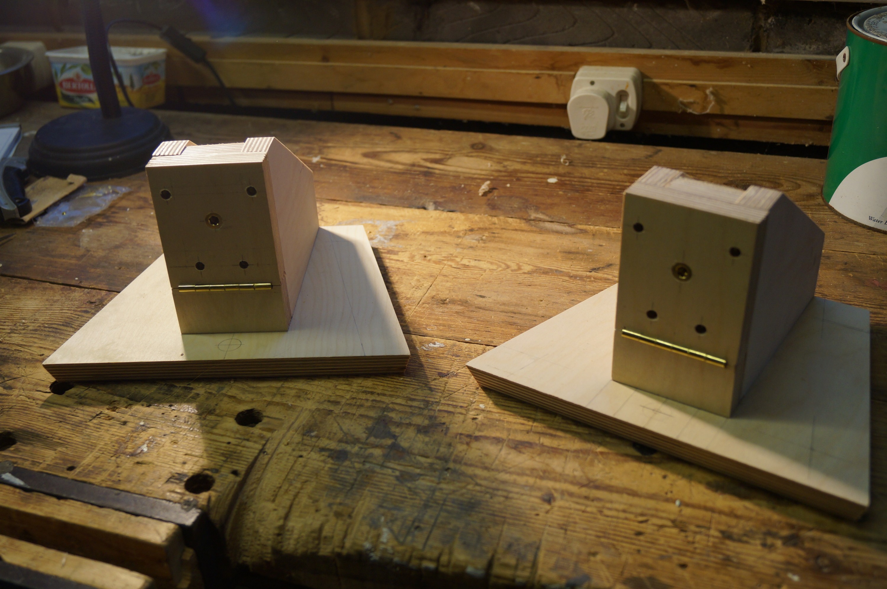
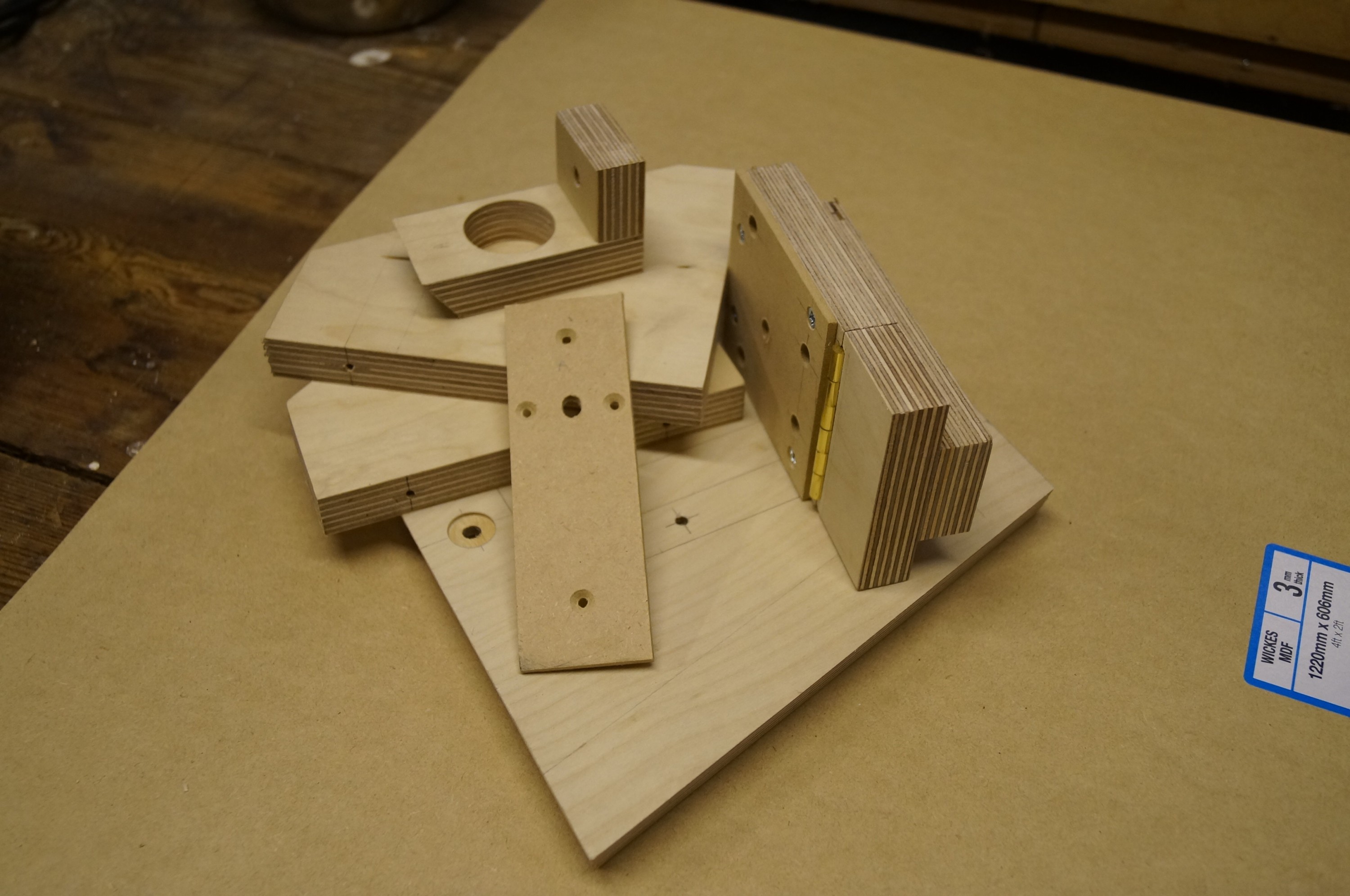
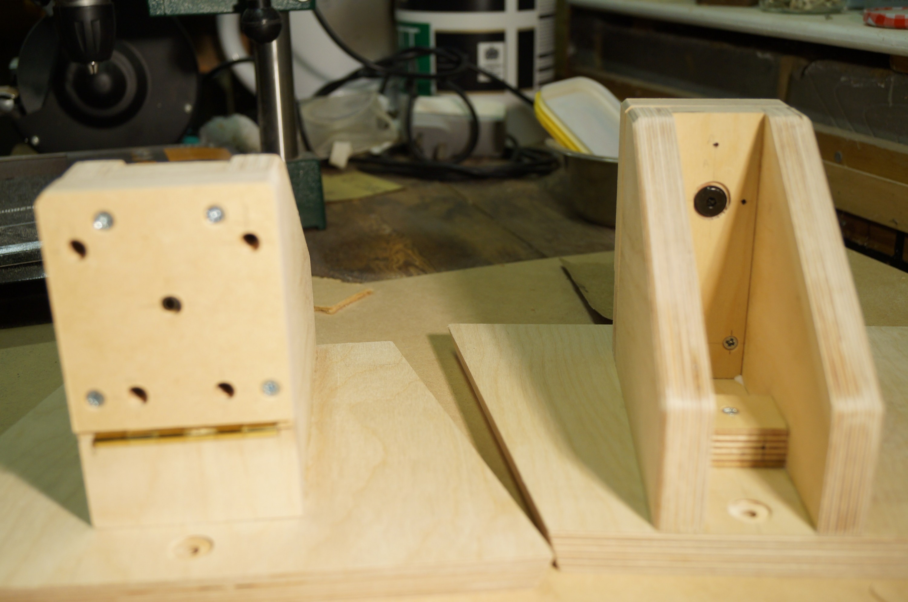
Tilt assemblySupports and bases
The photos show all completed parts sitting dry on the base. The LX521 baffles have a striking angularity, so I decided to go with this and plane the front and sides of the bases to an angle also. I like the look! – quite racy. I will do the same to the front and sides of the top of the bridge.
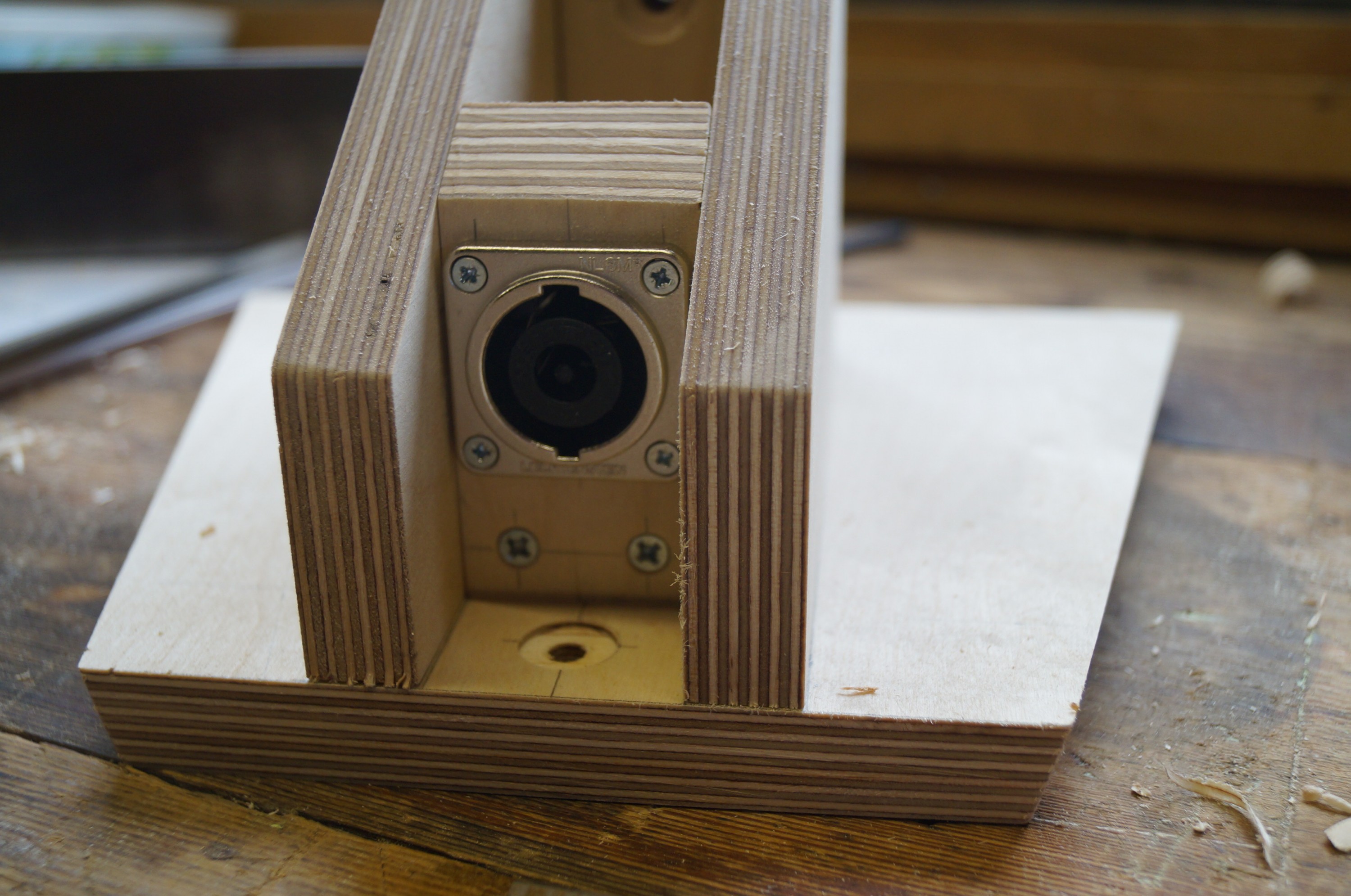
The Speakon bracketsMarking outTrial dry fit
The next job was to make some little brackets for the Speakon 8-way panel connectors; I didn’t have a 32mm wood bore so ordered a Bosch one from Amazon. It made a very neat job. I’m only gluing the horizontal component so I can remove the connector for wiring up – I don’t fancy digging around in what will be a black hole at the back of the support! The horizontal element will need careful positioning before gluing to ensure the bevel lines up with the support sides.
I still need to cut the front hardboard spacers together with the smaller oblongs that will be screwed to the back of the front assembly to act as a retainer for the adjusting bolt; they will have a hole just large enough for a hex screwdriver to engage with the bolt.
The last couple of days has seen further work on the baffle supports – these are now all screwed and glued and (bar the Speakon brackets and the small hardboard covers) sanded and primed. They are looking good.
Glue-up had to be a staged affair (though not as laborious as the woofer boxes!), the main challenge being to ensure the sides were nicely square to the bases. The hardboard components are also shown here; the spacer is screwed onto the hinged element, and the narrower piece will go behind the front plywood components to retain the head of the bolt controlling the tilt.
Second side onBoth supports complete
I found it easier to assemble the supports “sideways” initially with the bases clamped in the vice. The sides are each secured with two 2″ x No 8 screws inserted via the bottom of the base (not visible in my pics). The base of the Speakon brackets acted as a useful spacer when glueing the second side. I glued the sides, front elements and bracket bases together first, using wax discs again to keep the joints to the base glue-free so I could then unscrew the vertical assemblies from the bases to plane off any imperfections – planing options are limited once they are glued to the bases. Before gluing I had used a 12mm wood bore to lightly recess the front and rear fixing bolt holes on the bases.
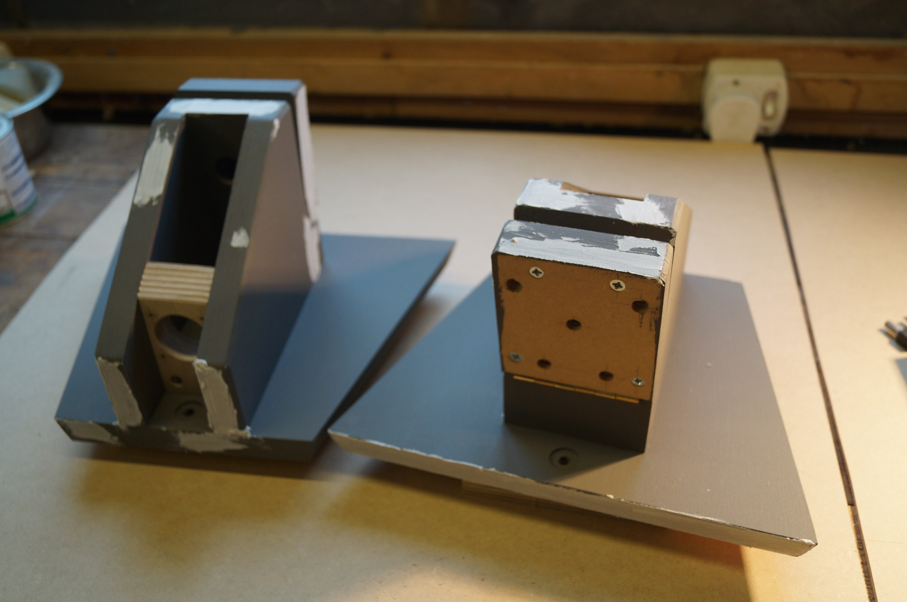
After initial priming and filling
After two coats of primer and some sanding and filling I found that the hinged elements were binding slightly on their lower edges when in their closed (vertical) position; this was easily solved by slackening and re-tightening the hinge screws which allow just enough play for fine adjustment.
The top of one of the small hardboard bolt retainers was a little proud so I took the plane to it – a bit too heavily, as it promptly snapped in two. They are fairly fragile. It too 10 minutes to mark out and cut a replacement, which fitted better than before, so nothing lost except a bit of dignity / pride!
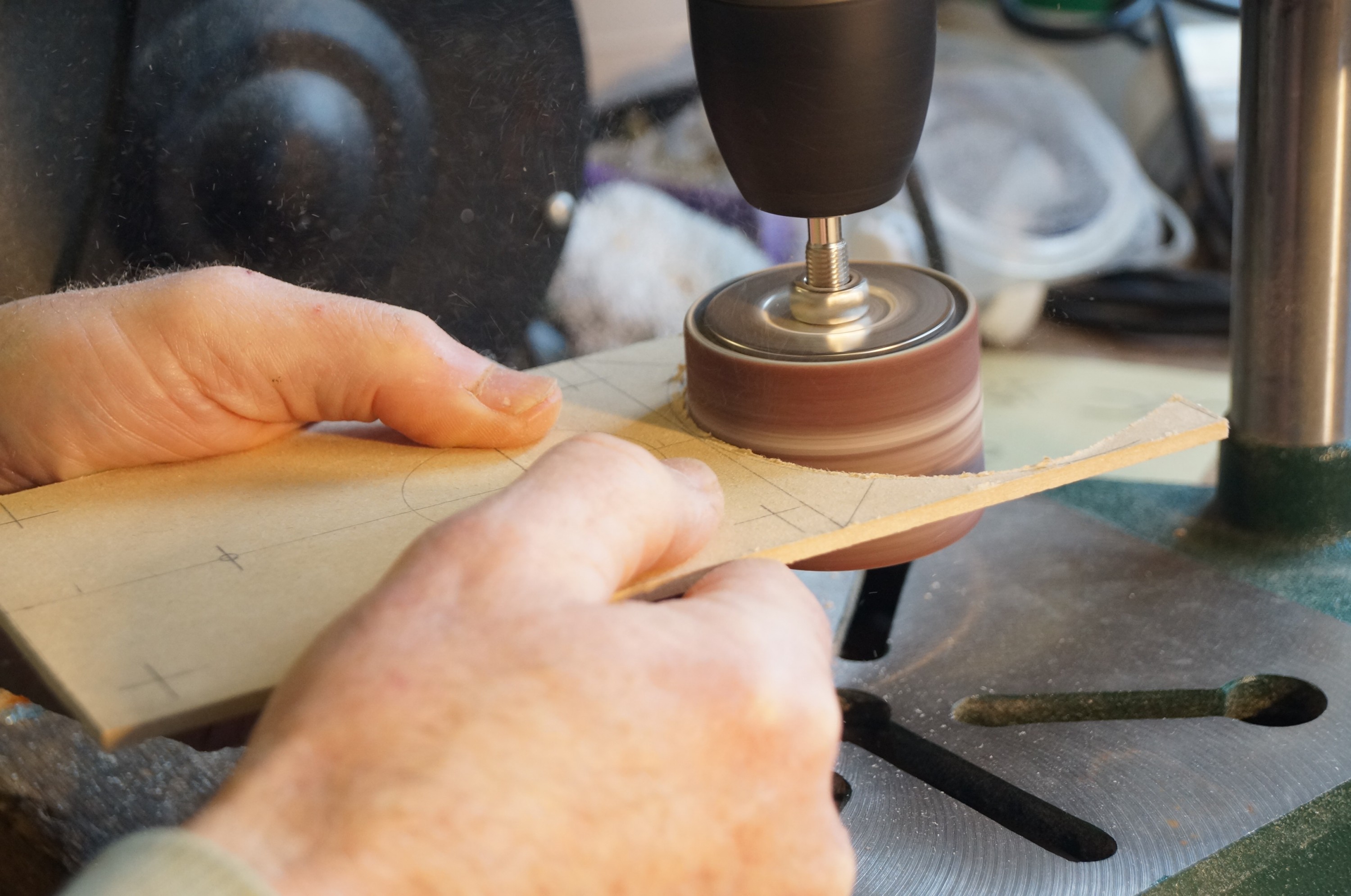
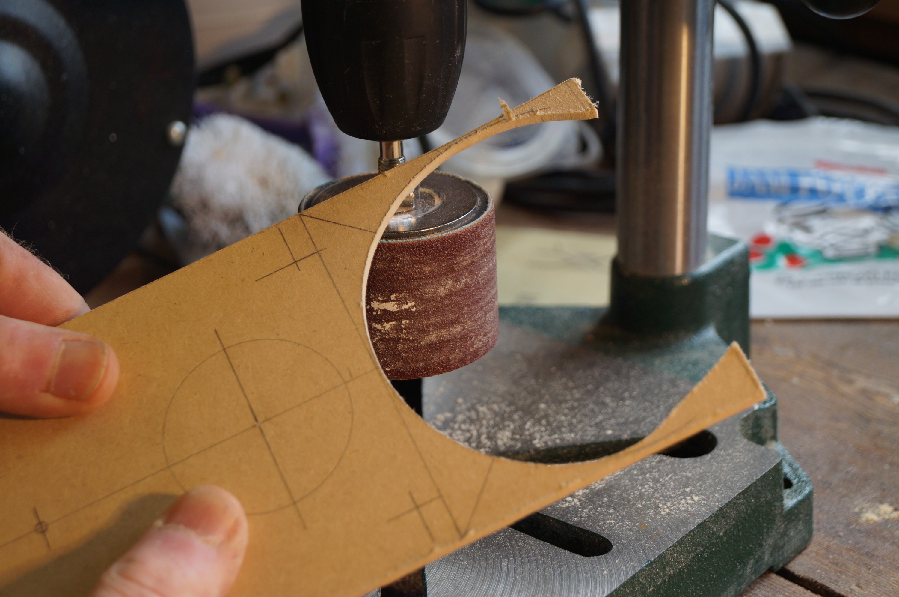
Drum-sanding to lineAfter drum-sandingCutting the mitred corners
Today I made the tweeter baffles. These are fiddly because of the lower curve that frames the upper midrange unit, and I was a little apprehensive about how to obtain a neat job.
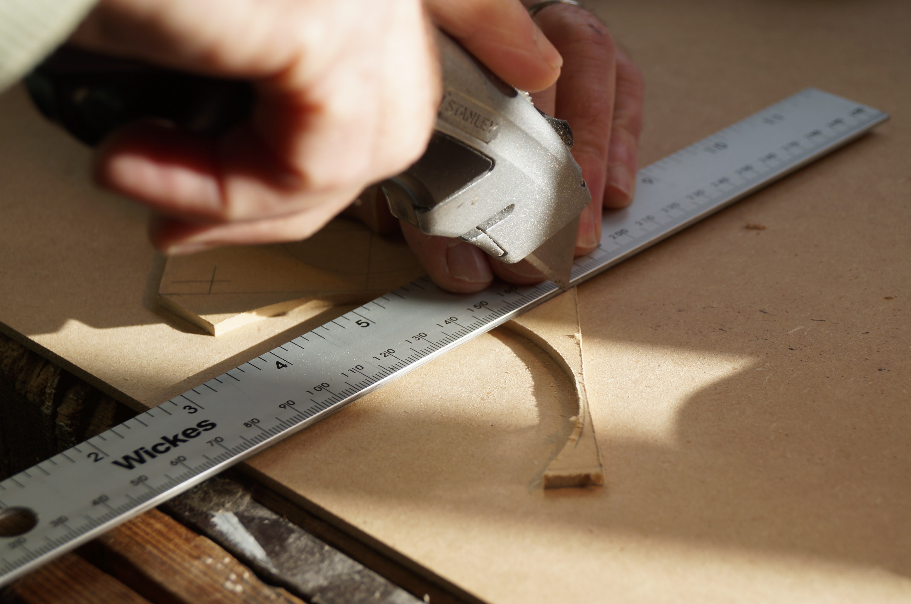
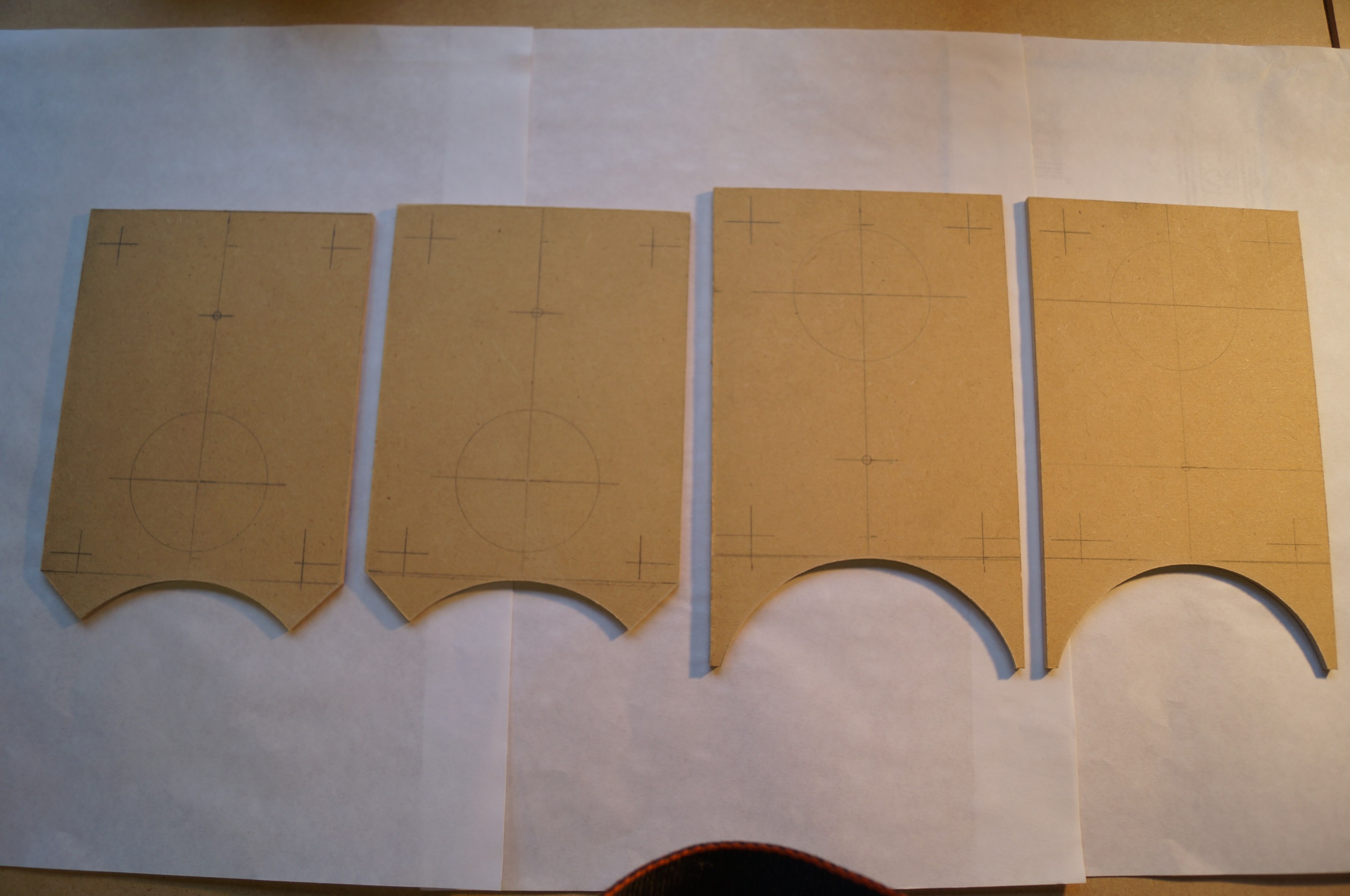
I first cut out the baffles with a Stanley knife and a metal ruler; the 3mm hardboard needs 8 – 10 passes with increasingly firm pressure to cut very cleanly. I then clamped all four baffles together and rough cut the curves with the jigsaw. I then gently took the hardboard back to the curve line using my trusty little Screwfix drum sander mounted in the drill press. This has been an excellent buy and has rescued several awkward moments. In the end the job was far easier than expected and they all came out neatly.
All that remained was to cut the bevels at the lower edge for the front facing baffles; I adopted Bill Schneider’s idea of giving the rear baffles a different look. The final task was to lightly bevel the top and sides with the plane. Really pleased with how they came out.
Shaping complete
I’m keen to get on to the hardwood baffles, so before finishing for the day spent some time marking out my 7.5″ cherry board (which I had bought months earlier at the same time as the drive units) for the two panels; this will involve cutting and glueing two short 3″ wide boards to either side of the lower ends.
Initially I had planned to assemble the cherry boards with dowels to add strength, but after an experimental first joint decided to ditch the dowels; despite my most careful mark out the joint was slightly out of true. I had not realised how easy my new aluminium clamps would make the procedure, as these supported the boards perfectly during glueing. I left them clamped for several hours after which joints were rock solid and well aligned, requiring minimal planing off to achieve an impalpable joint line.
First panel assembly
One baffle panel has a minor concavity because of a slight warp on the main central board, so I planed down the side boards by about 0.5mm to reduce this. It certainly won’t be noticeable without getting a straight edge out and I don’t anticipate a problem when it comes to mounting the drive units.
Once the planing was done I was able to retire to the kitchen to finish all the marking out. I plan to have all drive unit and screw / bolt holes drilled and and prepared before cutting out the finished baffle shapes – another job I am apprehensive about!