Gluing up and filling

1. Top to front flap, followed by both to side (not shown)
2.1 Filler to upper V-frame

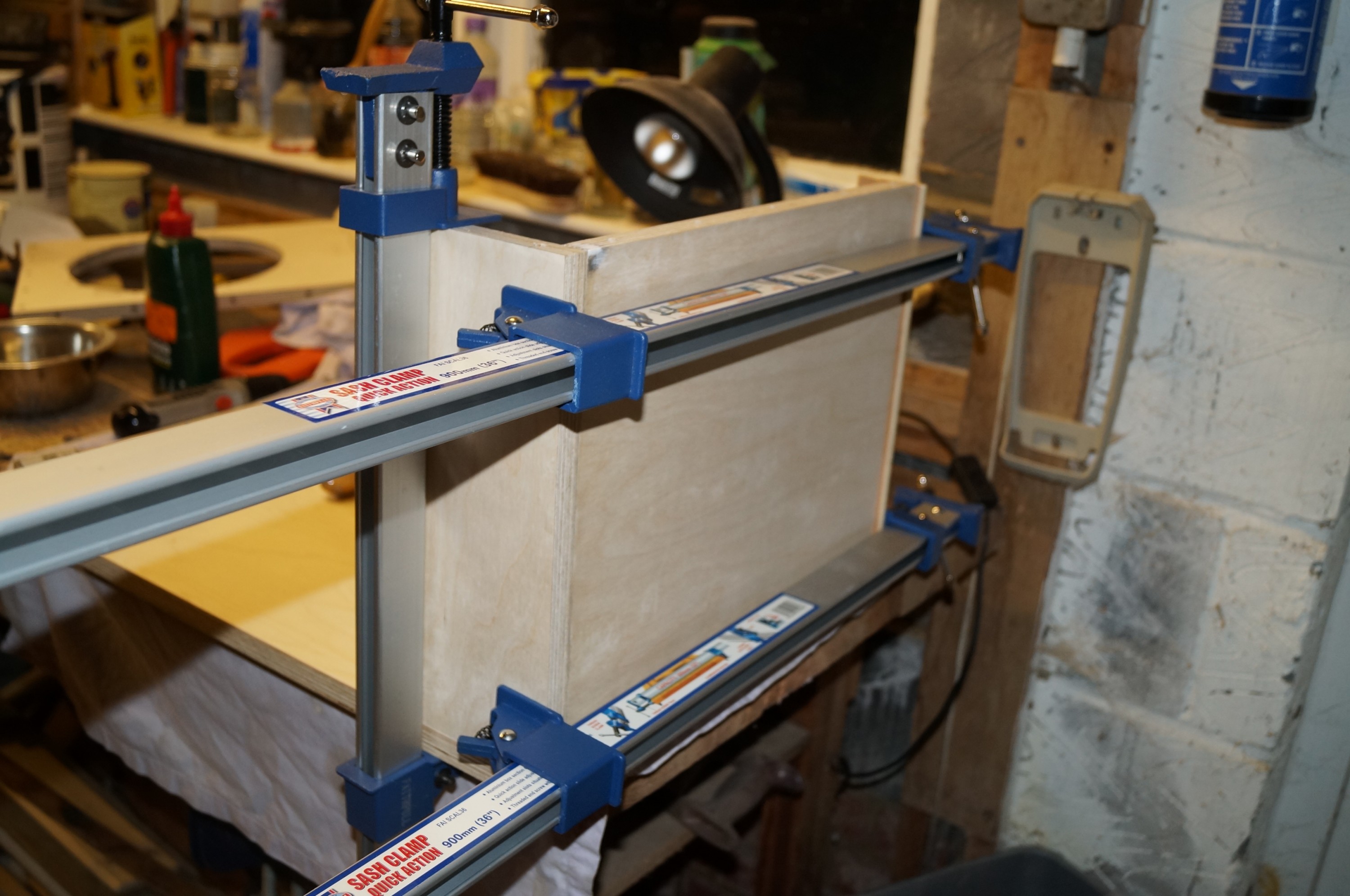
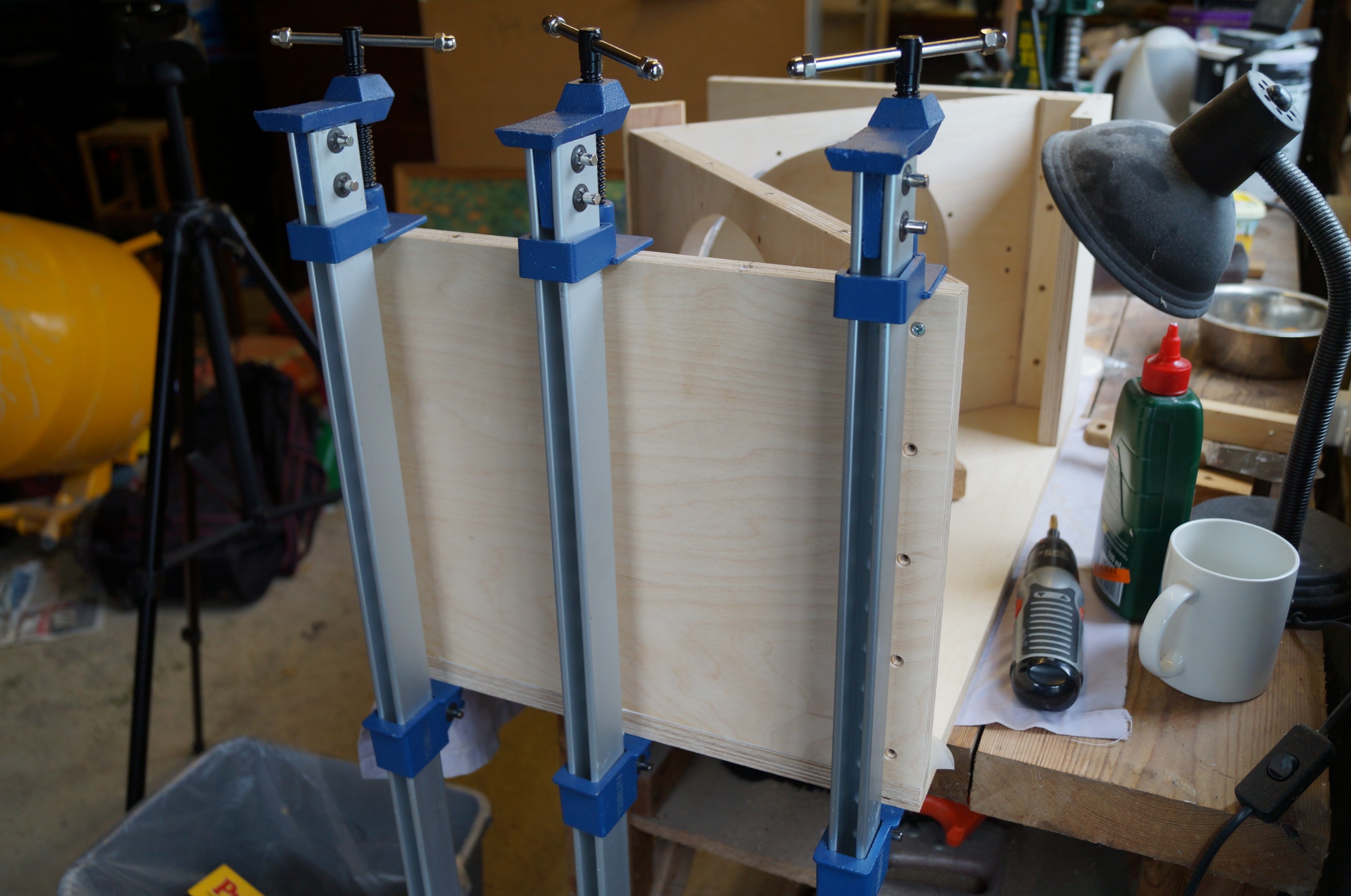
Good progress since last post – both woofer boxes now glued and screwed. The process was not without incident, but no major glitches. I was glad I had invested in some aluminium sash clamps, although soon found myself wishing I had ordered six rather than four.

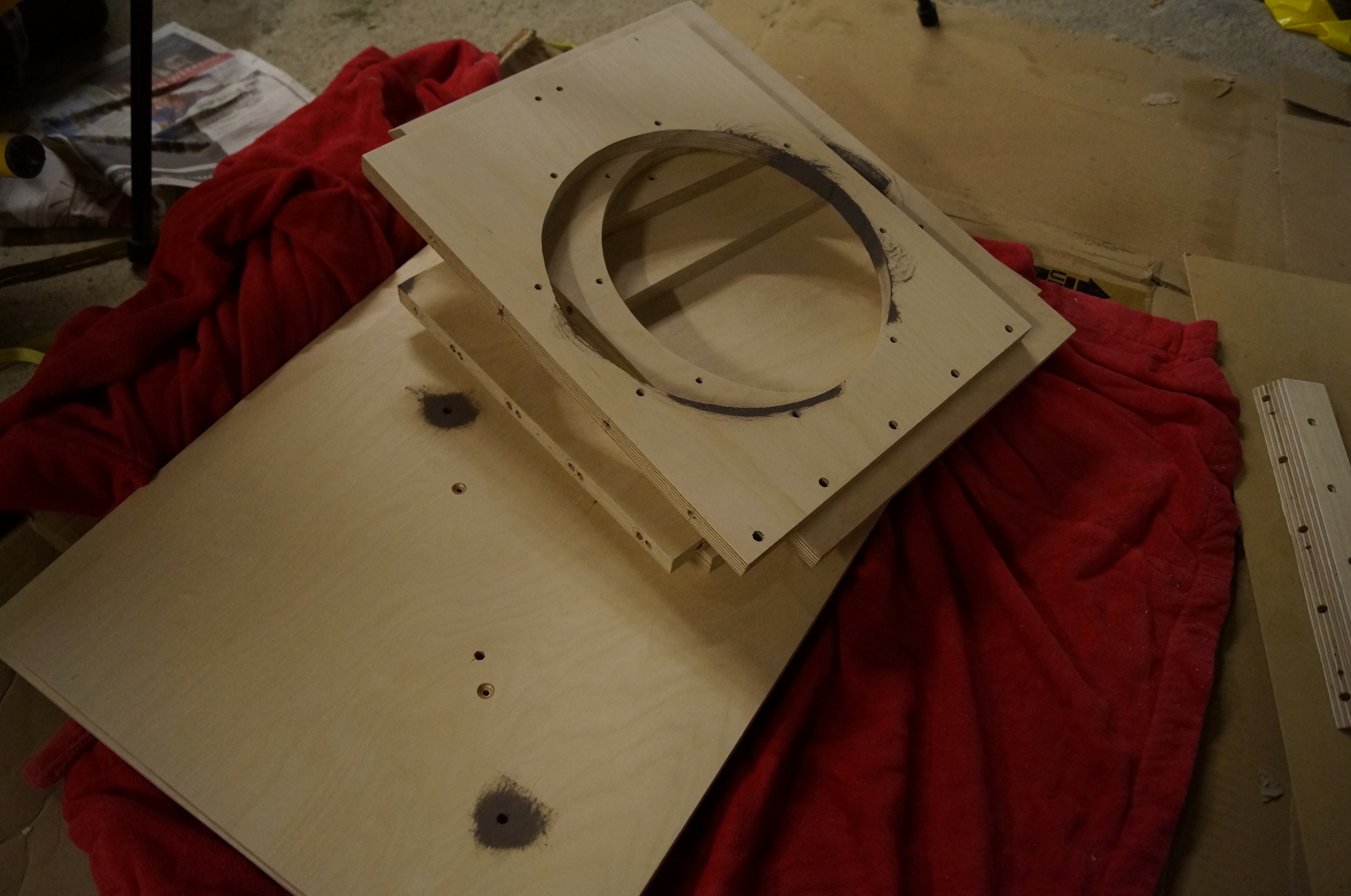
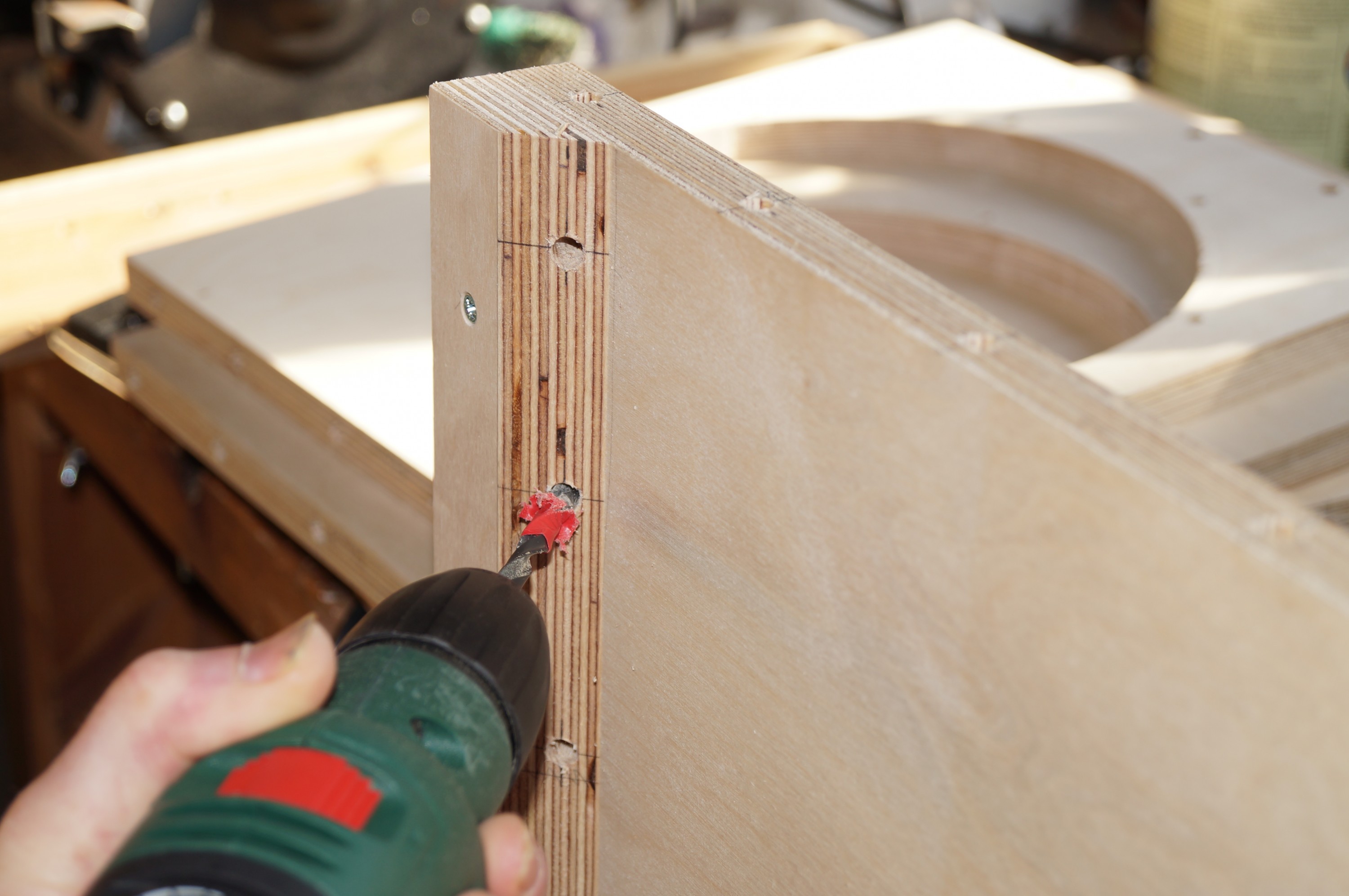
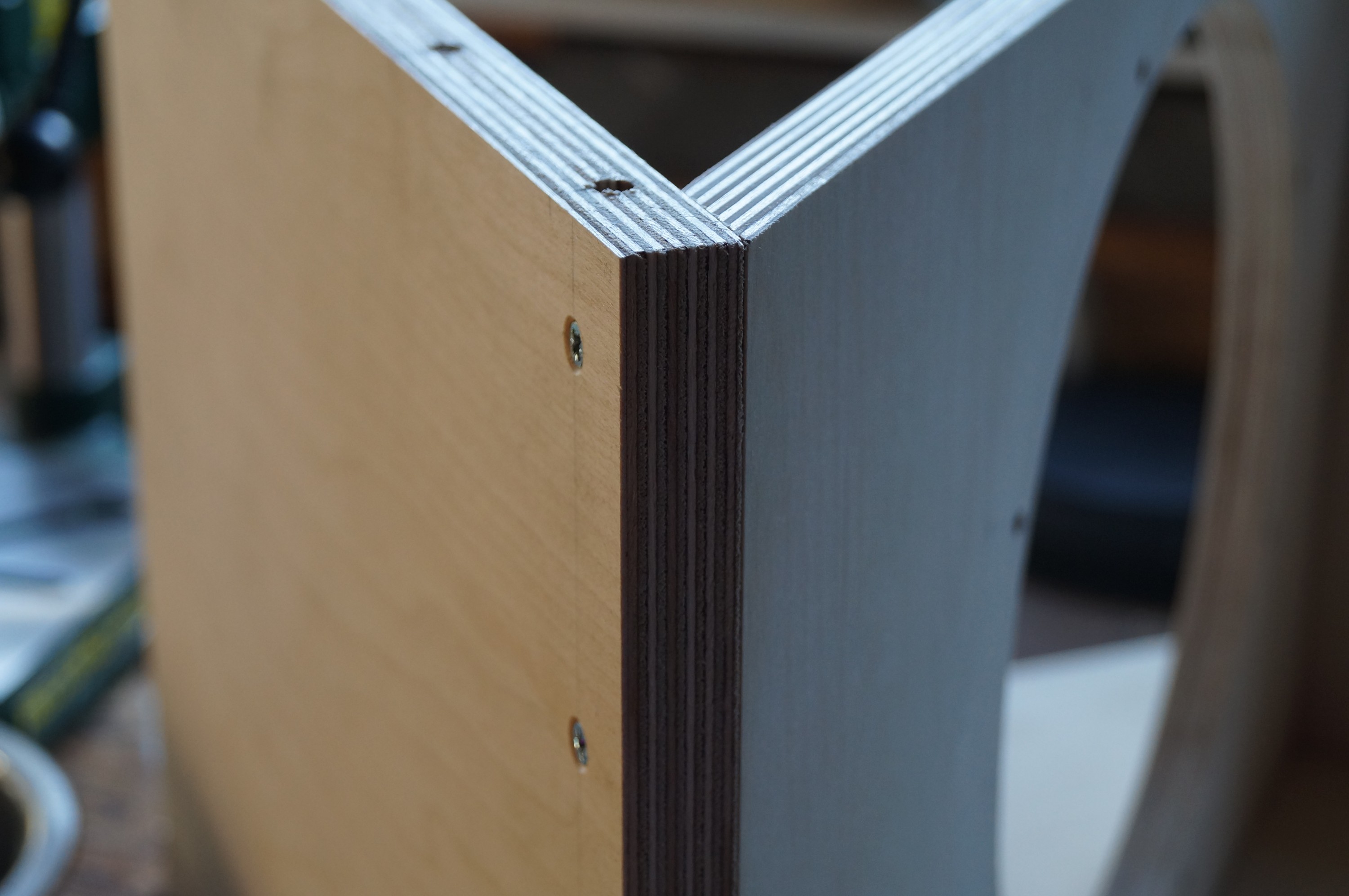
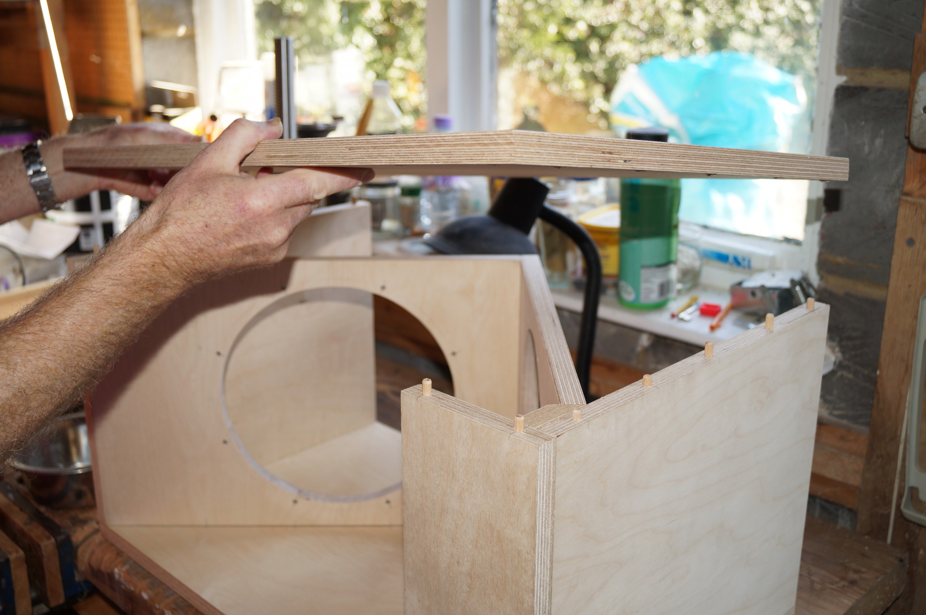
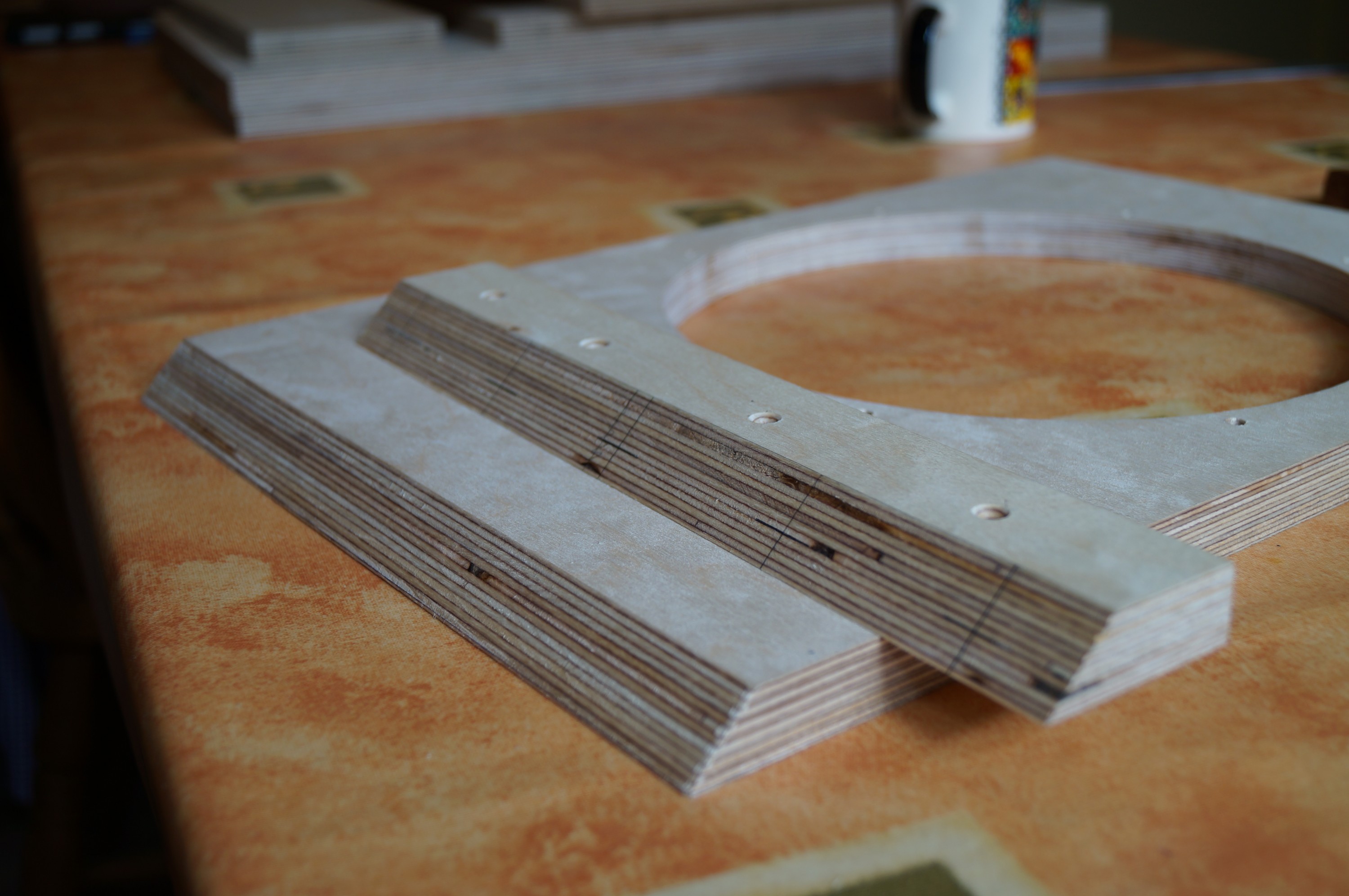
I knew that order of assembly was important from thinking about this as well as perusing other audiophiles’ build logs (notably Bill Schneider’s meticulous record). Using dowels to strengthen the joints between the V-frame and the sides makes assembly order critical, as all V-frame elements have to be assembled and glued before lowering these onto the side dowels. The photos show the order I adopted.

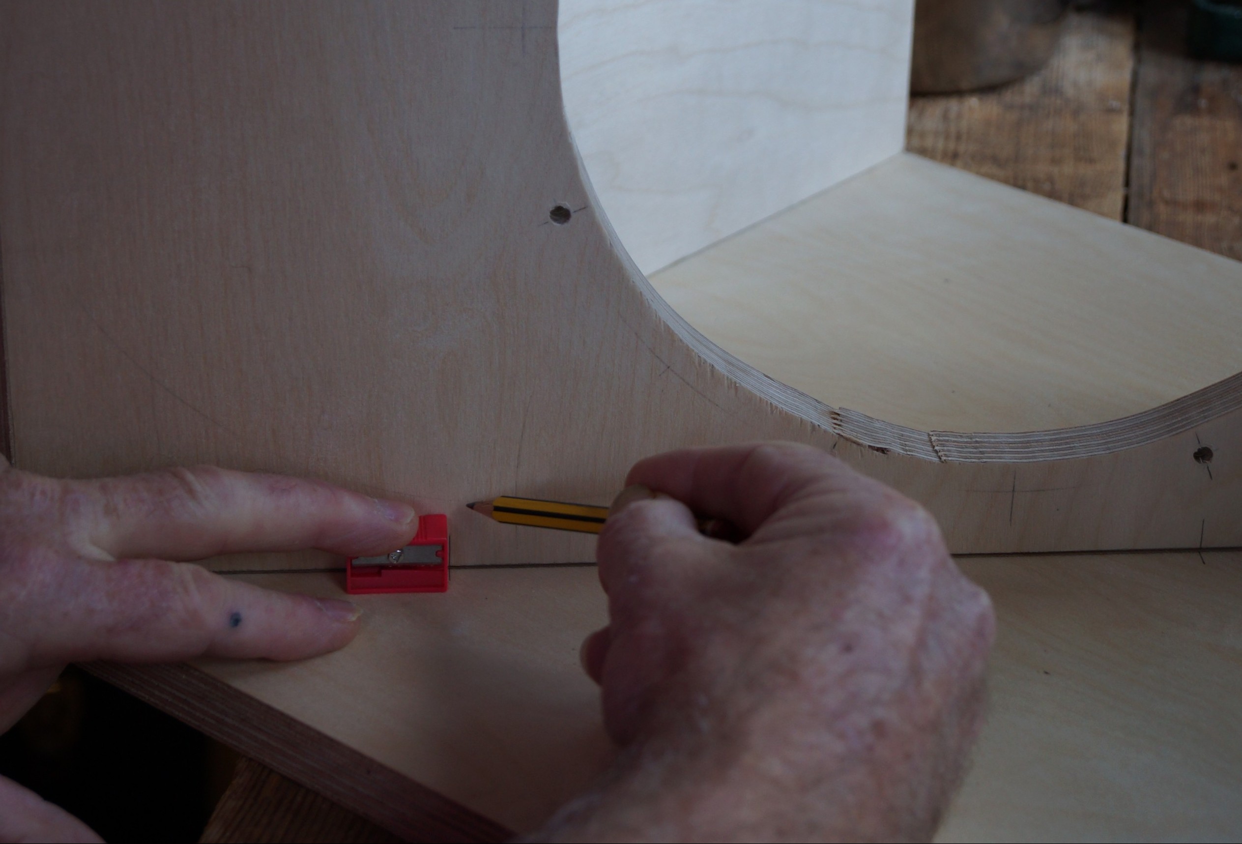
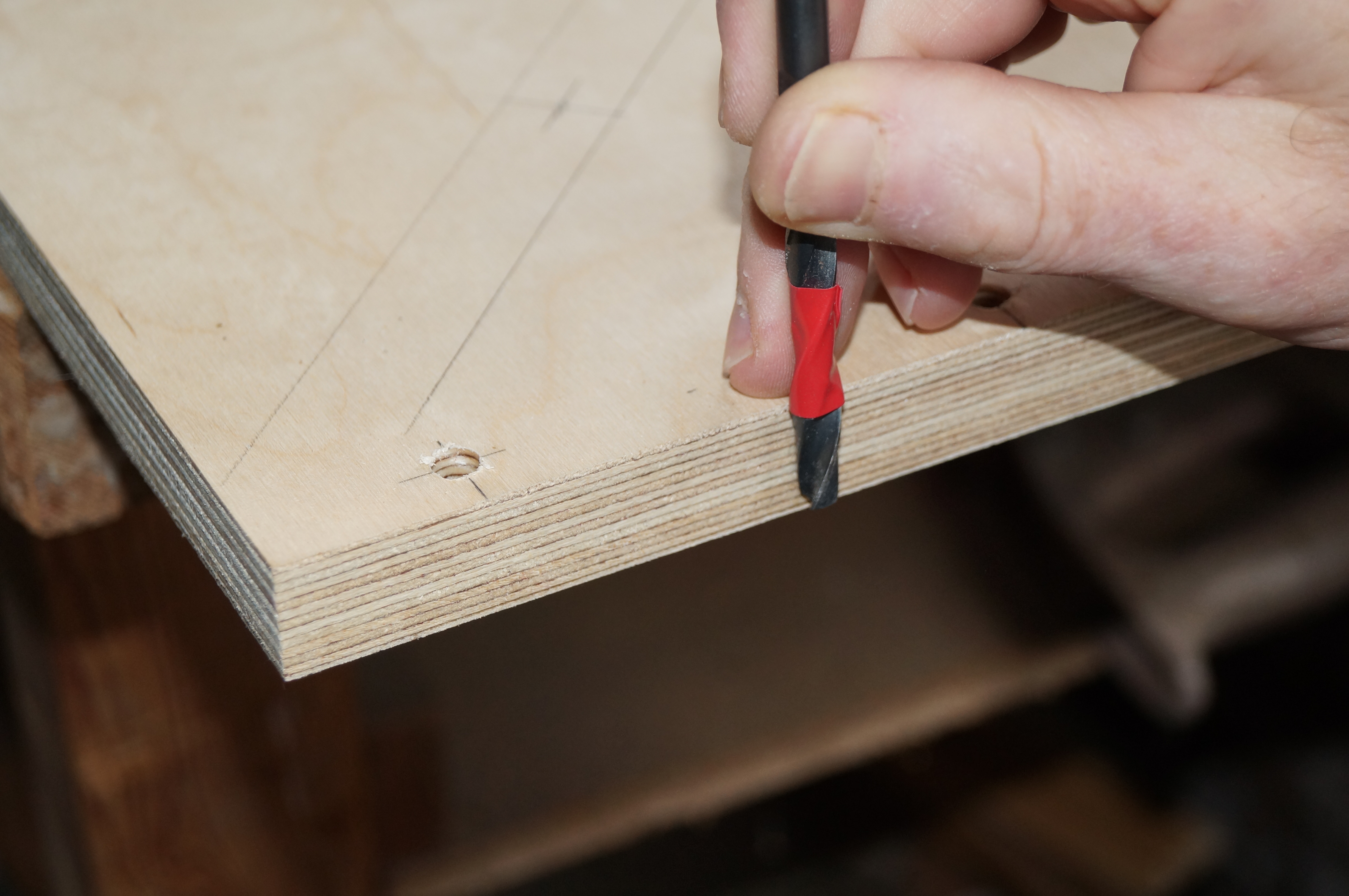
When assembling the first box I discovered (after priming dowel holes with glue!) that the slightly proud through-dowels between the upper V-frame and the small filler behind the front flap prevented me from dropping the V-frame assembly in place! – I had anticipated sufficient play to allow this, but no…

2.2 Planing off protruding dowels

Some rapid planing off of the protruding dowel ends rectified the problem.  This apart,assembly proceeded uneventfully.


3. Upper to lower V-frame (located on dry side dowels)


4.1 Bottom to side (dry-screwed to lower V-frame)


4.2 Wax disc to keep glue from dry joint

I used waxed discs (as used for preserves) to confine the Evostick to the joint being glued during the staged assembly; another good idea from Bill Schneider.


5. V-frame assembly lifted out before gluing up side dowel joints

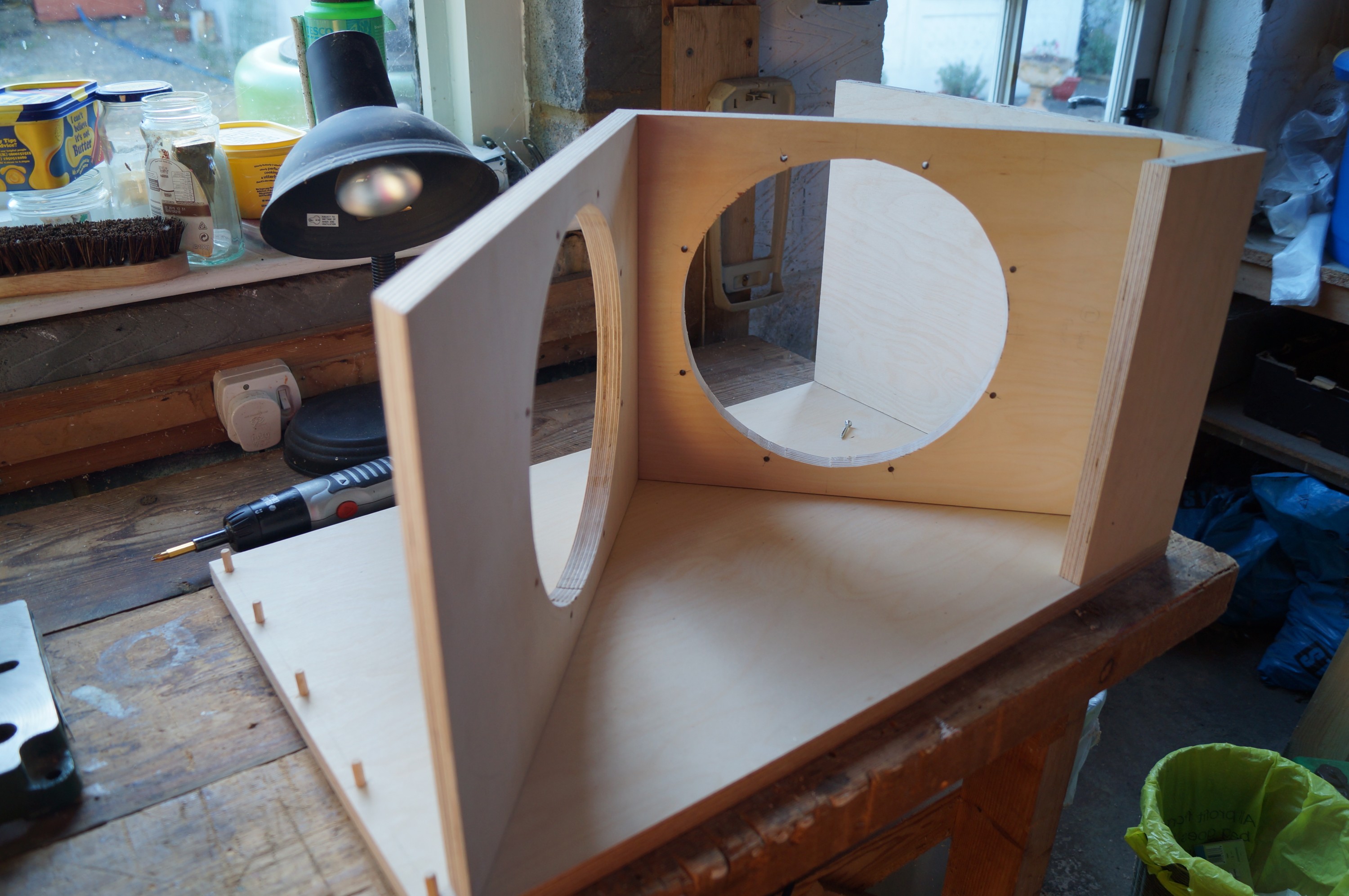
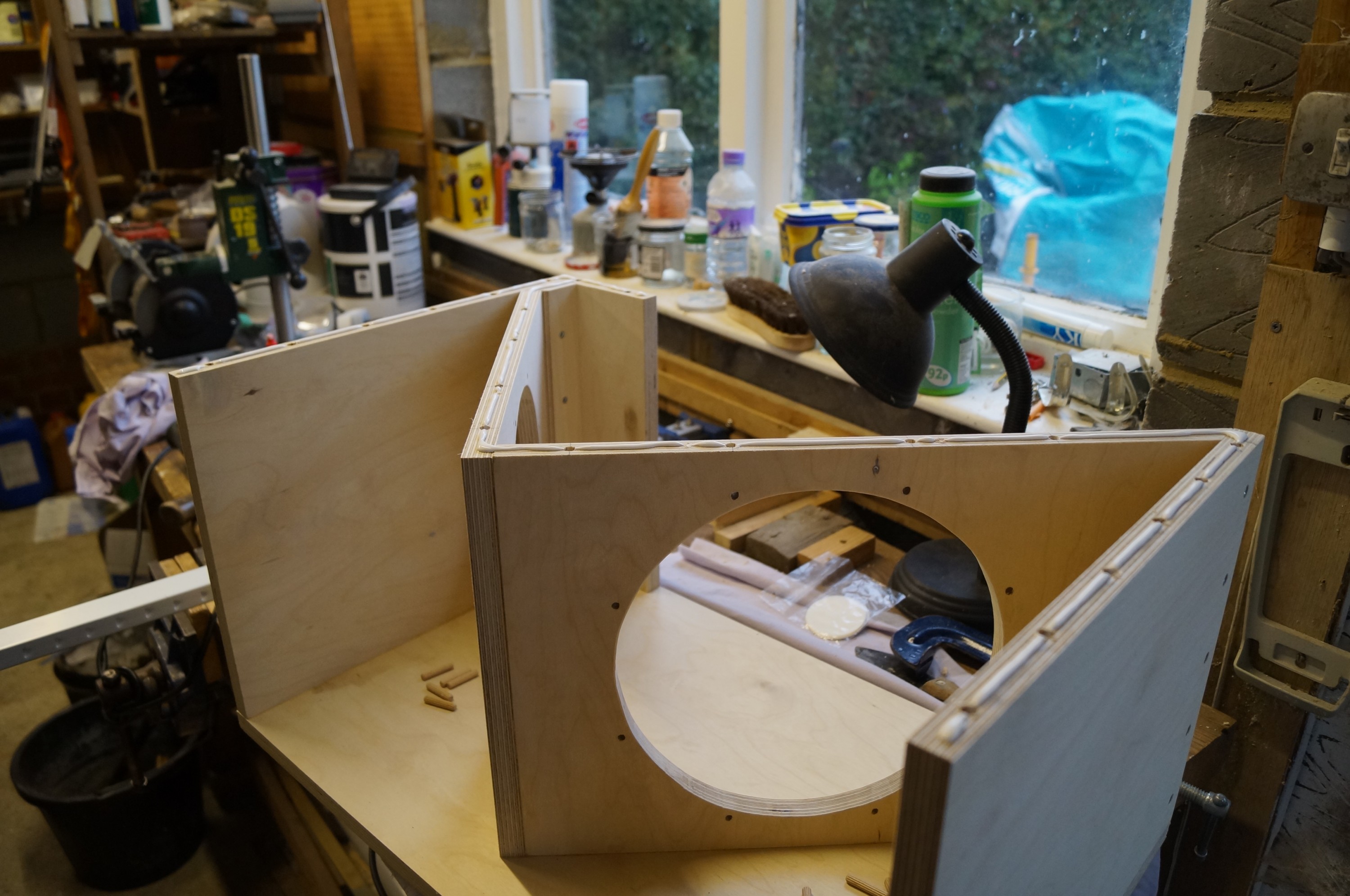
The dowel-glued V-frame assembly, shown separately here, felt extremely strong with minimal give – I was glad I had decided to glue it in place using the side dowels to ensure correct alignment. Its stiffness was what led to my protruding dowel problem!


6. Checking fit and assembly before gluing and screwing V-frame in place

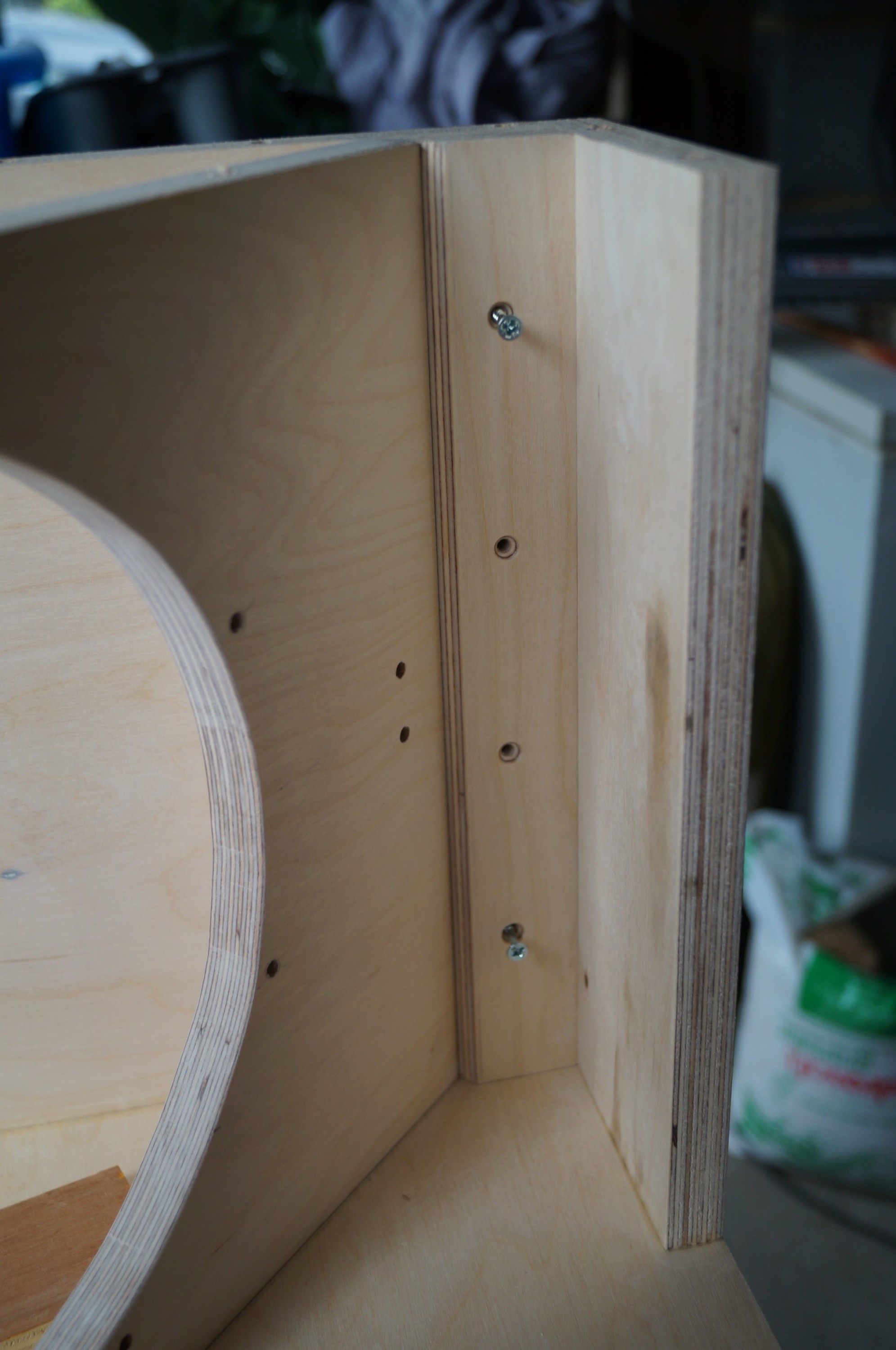
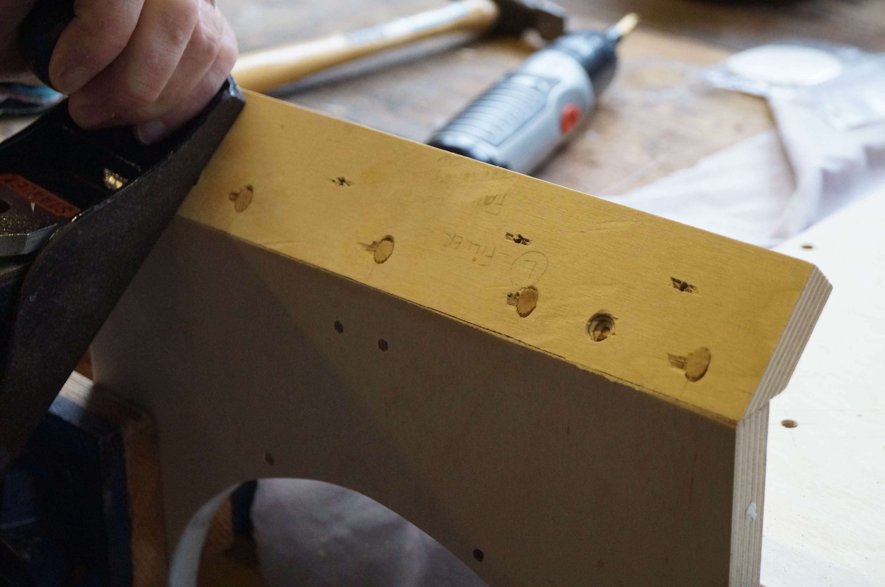
This shows the underside of the front flap and mitred filler piece; I used screws here (impossible to clamp), and I won’t be filling these in their concealed position.


7. One side done; gluing up for other side

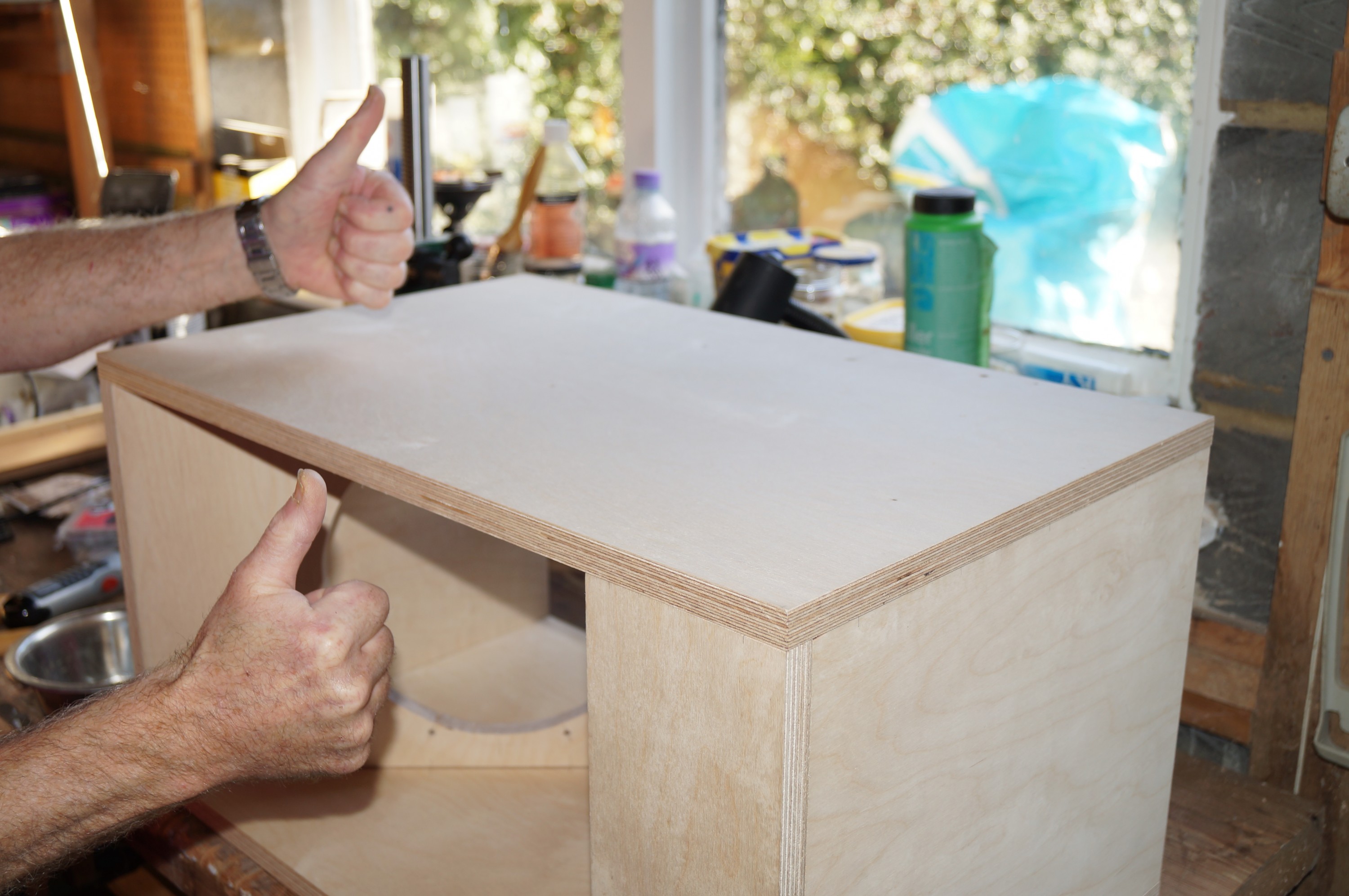
The boxes came together reasonably well and square; the 2″ x 8 screws countersunk into the sides pulled the V-frame side joints nice and tight.


8. Second side glued and screwed - assembly complete!
8. Second side glued and screwed – assembly complete!

Some planing was needed to top and bottom to bring sides flush before final sanding. I did have to fill the front flap on one box as the lower edge ended up a millimetre displaced backwards. I spot primed these areas together with all countersinking and other minor surface defects before filling.


I had researched wood fillers before commencing the build, and had settled on Toupret TX110 filler (the French like to finish stuff properly). It needs a few hours to develop full strength but it cures very solidly and sands beautifully flat thereafter – a good buy. Filling and sanding the countersinking on the sides and bottom completed the making good.

Sanding and spot priming

Sanding down surfaces

I am impatient to get on with the gluing up, however the advancing years have happily brought reserves of patience I  was certainly not in touch with as a younger man. Preparation, preparation! I sanded down all the flat surfaces today, using 80G, then 120G – the nooks and crannies in the completed woofer boxes make this nigh impossible after assembly.


Marking U-W wire holes
Will be hidden by front flap

I was pleased that I remembered to drill holes in the upper V frame to take the upper woofer wires through to the rear.


Spot priming done
Spot priming done

Last job of the day was spot priming various surface imperfections (and my unintentional through-holes) prior to filling tomorrow. I have decided to make life easy for myself by going the acrylic route, and I’m using Bedec grey primer. I’ve also bought tins of Bedec matt black and satin black top coat as I don’t know which will look best – I can use the same stuff for the tweeter baffles later.

Woofer joinery details

Drilling face holes
Drilling face holes
... and edges
… and edges
Srew to top and deepen

A few photos of construction details.

Apart from those anchoring the V-frames to the sides, screws were used only in hidden areas, namely the filler behind the front flap and the lower V-frame joint with the bottom.


Drilling dowels on the spacer


Drilling dowels for the upper V-frame mitre joint.


V-frame in position
V-frame in position
Lower V-frame joint detail

Setting out V-frame and bottom mitre joint. I drilled a 5-dowel joint between upper and lower V-frame elements.


Second side dry fit
Second side dry fit
Marking side dowels
Marking side dowels

Fitting “top” side before marking out V-frame dowel positions.


Final dowel mark-up
Final dowel mark-up
Perfect fit!
Perfect fit!

Squaring across marks and centring at 9mm.

Woofer construction

MATERIALS

DSC04156
The first box – “flat-pack”

The woofer boxes are made from 18mm BB grade birch ply – I sourced these from Woodcraft in St Neots as they offered an accurate cut-to-size service, with a tolerance of around 0.5mm. I had redrawn the woofer plans converting measurements to metric (details not given here as copyright to SL).


The planed mitres
The planed mitres

When I picked up the order (plus offcuts – needed for the upper baffle mount) I was pleased to find no planing was required at all, and all panels were nice and square. Good decision. I had already marked and jig-sawed out the woofer holes and drilled their mounting holes before I got to grips with Wordpress; bar the dowels the only other preparation was to plane the45deg mitres on the lower V-frames and the top filler pieces.

SCREWS OR DOWELS?

I decided on dowels partly because of the considerably increased strength these impart, and partly to keep the external surfaces as pristine as possible for the sake of a good finish. I am aware that some building the LX521s have opted for screw and glue; in the end perhaps it is a trade off between spending your time marking and drilling dowel holes or filling endless countersunk screw holes.

DOWEL JIG OR MARK OUT?

Dowel jig
Dowel jig

My next decision was whether to mark and drill them all individually, or whether to fabricate a jig to speed the process. Some experimentation followed; this is the Mark 2 jig made from some spare hardwood which I used to drill the first box. Modified rapture  – despite carefully screwing the jig to each joint line I experienced some unpredictable drill wander. Some joints came out perfectly whereas others were distinctly off, requiring tedious adjustment of dowel holes to bring things back into line.

Guide holes before drilling

I therefore decided to ditch the jig for the second box in favour of the more traditional approach  – painstaking marking out of dowel positions with a very sharp pencil. At least this could be done in a warm kitchen. For accurately positioned dowels the trick was to use a bradawl to mark each one with a small hole before drilling; this held the drill position well. Tedious but worthwhile; the second woofer box came together almost perfectly with minimal adjustment required.

Setting drill depth
Setting drill depth

Dowel hole depth is obviously more critical drilling perpendicularly into the flat surfaces. I used insulating tape round the drill bit to mark approximately 15mm. Having smugly taken a photo of this I promptly drilled right through one of the sides – twice! I was rushing, and was drilling too quickly. Ah well, nothing the Toupret filler won’t rectify later (and the sides are hidden by the bridge anyway).


Background

This is my build log of Siegfried Linkwitz’s latest and best open baffle dipole loudspeaker design – the LX521.4.

My relationship with SL’s designs goes back a fair way… my good friend Pete Johnson at medical school drew my attention to Siegfried’s Wireless World active crossover system some 30 years or more ago – we both decided to build one. Pete was a whizz at electronics, whereas I was more comfortable working with wood (thanks, Dad!). Last year for some reason I found myself wondering whether Siegfried was still alive and active in the audio field and searched out his website . It did not take me long to decide to build the LX521s – my old WW system had fallen into disrepair and had been consigned to the garage years earlier (I have renovated it since – separate page to follow).

I hope the log will both inspire and help others to build their own LX521s. I’ve not even heard them yet! – but everything I have read suggests I won’t be disappointed when they are finally up and running.

Click on any thumbnail to see full photos.